


Homepage » Surge Protection for Energy Storage Systems (ESS)
Created by: Glen Zhu | Updated Date: September 6th, 2023

As demand for electricity becomes ever greater, the need to store energy (as well as produce it) also does. Like all electrical installations, energy storage systems need application-specific protection.
Energy Storage Systems (ESS) are now a mature technology. ESS is installed at sites to improve energy management control, such as peak management or frequency regulation, or for renewable energy storage for photovoltaic or wind-generated energy applications.
The importance of such equipment makes interruption of their service unacceptable, so measures must be taken to limit damage due to external influences. One of the risks to be taken into account is possible damage due to transient over-voltages generated by lightning or by switching operations.
The deployment of ESS has demonstrated the limited robustness of these equipment, including battery systems. Specialists in this technology have ascertained that their low impulse voltage withstands (Uw) may lead to critical system failure.
Surge Protection Device (SPD) technology is widely used in AC power networks to protect equipment connected to them against transient over-voltages.
Test standards (IEC61643-11), and selection and installation guides (IEC61643-12, IEC60364-5-534) have been in existence for many years. They define reliable products as well as their selection and implementation.
However, regarding DC power networks, neither standardization is available at the time of writing. In fact, the standards for surge protection for DC power are ongoing at the international level (IEC).
It is, however, expected that by the end of 2021 the following standards will be in place:
This forthcoming standard IEC61643-41 will be extrapolated from existing standards of surge protection devices for AC networks (IEC61643-11) and the sizing parameters (In, Uc, Imax, Up …) and test procedures will be similar because they will be grouped in a new document, common to the two documents.
The IEC 61643 series is moving towards a new philosophy. A new document (IEC61643-01) will gather all the definitions and tests common to the various applications of SPDs (AC power, PV power, Dataline, DC power) and the dedicated standards (IEC61643-11, IEC6163-21, IEC61643-31, and forthcoming IEC61643-41) will focus only on the specific tests for the application.
Regarding safety tests that simulate the end of life of the SPD – such as thermal runaway or short circuit behavior – the procedures are similar as well as the necessary means to achieve requirements, namely the use of internal disconnectors to withstand the thermal runaway tests, and associated fuses to withstand short-circuit tests.
Regarding the obligation of protection against transient overvoltage for ESS equipment, the current standard for electrical installation IEC60364 doesn’t give information, requirements or recommendations on this point.
The reason for this is that IEC60364 addresses only low-voltage installations connected in AC power applications (not DC current), and it enforces protection requirements against surge voltages solely at the entrance to the outside network. This isn’t the case for the localization of the DC part of ESS.
Specialists in ESS equipment have noted reduced robustness in impulse overvoltage of these equipment – particularly in battery systems – and due to the imperative need for continuity of service, they recommend the use of surge protectors at their terminals. Surge protection on the AC part is also recommended.
For the following reasons and consequences, the critical point is the protection of the battery storage system. When the maximum DC operating voltage is very high (1,000 Vdc and more), in such cases a specific SPD is necessary, it being compatible with these voltages and in conformity with the future IEC61643-41. In cases of potentially extremely high short circuit current (100kA and more), the surge protector must withstand the short-circuit test is associated with a fuse sized accordingly.
To manage the short-circuit test, it is imperative that the surge protector is used with an external fuse. The fuse must be rated high enough to conduct 5kA at 8/20μs impulse current without opening but rated low enough to protect the surge protector during its failure on the short-circuit test.
Regarding the breaking capacity, this is the likely short circuit current calculated at the time of installation. Provided by the surge protection manufacturer, these requirements can make fuse rating selection somewhat difficult in the case of very high-power DC installations.
It could be considered to use the existing AC power SPD overload protection fuse upstream as protection of the SPD.
This is only possible if its rating is equal to or less than the value declared by the manufacturer of the SPD.
For high-power installations, the fuses have very high ratings, making this option a non-starter.

In conclusion, the key criteria for the selection of DC SPDs, extrapolated from AC standards are:
Battery storage systems store excess energy produced by Renewable Energy systems such as PV or Wind and store it for use when needed. This counterbalances the fluctuation between energy production and demand for electricity.
The importance of such equipment makes interruption of their service unacceptable, so measures must be taken to limit damage due to external influences. One of the risks to be taken into account is possible damage due to transient overvoltages generated by lightning or by switching operations.
Specialist manufacturers of Battery Storage Equipment have noted a reduced robustness in impulse overvoltage of this type of equipment – particularly in battery systems – and due to the imperative need for continuity of service, they recommend the use of surge protectors at their terminals.
Due to the maximum DC operating voltage often being very high (1000 Vdc and more), an SPD correctly specified for the application is necessary for it to be compatible with these voltages and in conformity with the forthcoming IEC61643-41. Due to the unique characteristics of Battery Energy Storage systems, standard DC or PV SPDs are not suitable for use with this type of application due to the potentially extremely high short circuit current (up to 100kA or more).
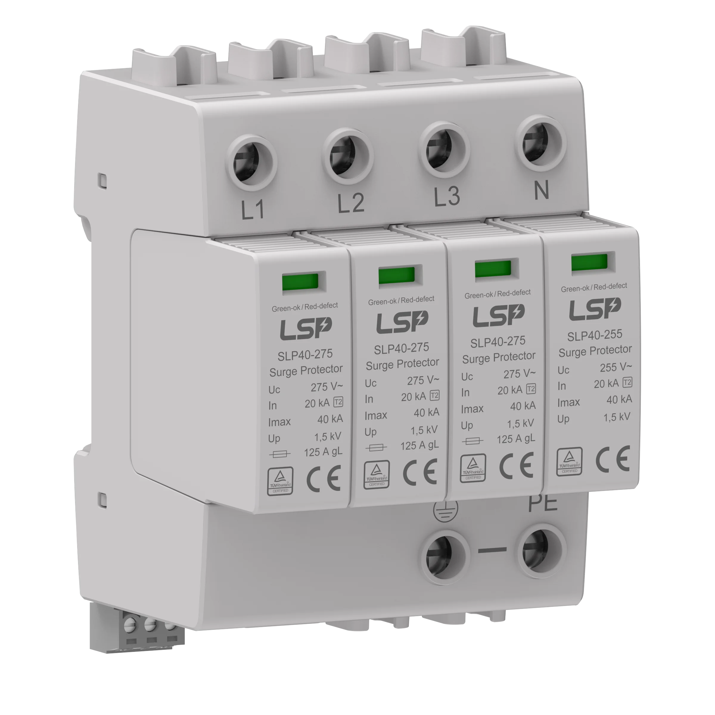
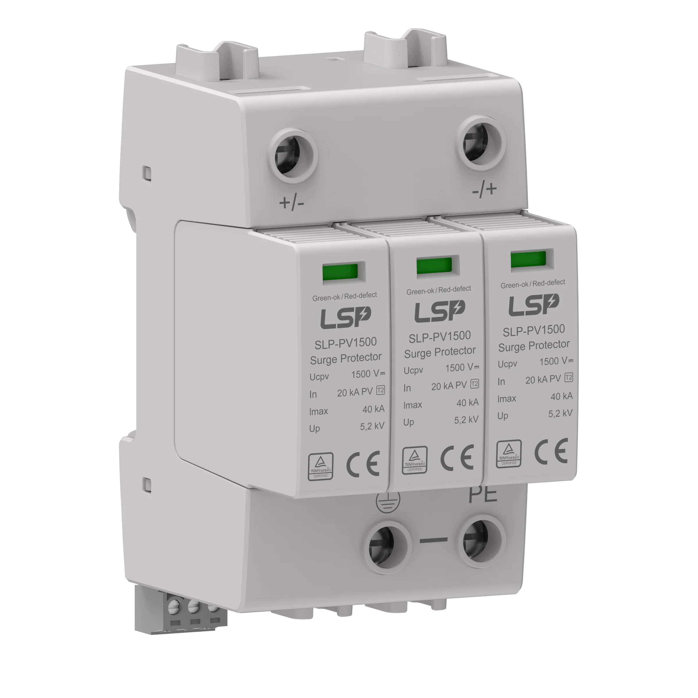
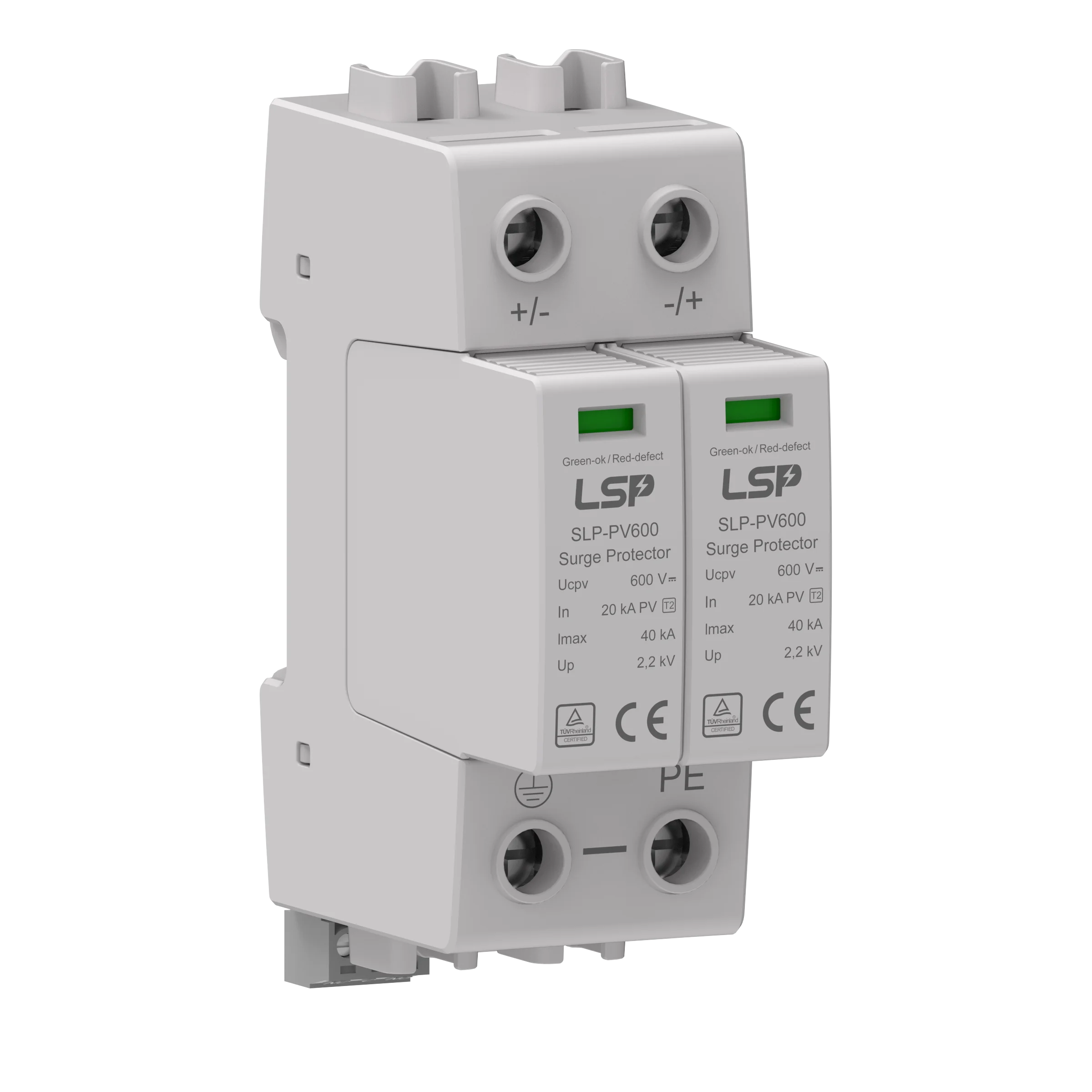
LSP has designed from the ground up the SLP-PV series specifically for Battery Energy Storage Systems. The SLP-PV series is a Type 2 SPD available with either 500Vdc, 600Vdc, 800Vdc, 1000Vdc, 1200Vdc or 1500VDC Max operating Voltage (Ucpv), an In (Nominal Discharge current) of 20kA, an Imax of 50kA and importantly an Admissible short-circuit current (Isccr) of 100,00A. It is DIN rail mounted and as such easy to install in any standardized distribution panel or control cabinets.
The SLP-PV series is part of LSP’s new DC range of SPD’s and is born from LSP’s 12 years’ experience in the manufacture of high-quality Surge Protection Devices. The range includes AC and DC Surge Protection Devices, available in Type 1, Type 2 & Type 3, for use with AC, DC and PV applications. The SPDs are suitable for use on all earthing systems including TN, TT/TN, TNS, and TN-C-S. The SPDs are available in Single Pole, Single Phase, 3 Phase, and 3 Phase & Neutral.
As one of the major power surge protection device manufacturers from China in surge protection, LSP has designed the SLP-PV series to meet the most extreme constraints, beyond that asked by the IEC/EN standards. In order to ensure total safety, the SLP-PV series is designed to provide a safe disconnection, high resistance to fire, and short circuit and built with high mechanical robustness.
The Energy Storage System (ESS) responds, either, to a financial issue to improve energy management (peak management/frequency regulation) or to an ecological issue pushing for energetic transition phenomena.
Through the energy storage system, green energy production becomes more efficient. The cost of facilities and the importance of the operation and efficiency of such equipment makes their loss of service unacceptable. Some measures must be taken to limit damages, due to external influences. One of the risks to be taken into account is the possible default due to transient over-voltages generated by the lightning or by the switching operations.
The risk of surge voltage can impact all the components of the installation, as well as the solar panels as the batteries or the network, which means protecting the installations from this phenomenon.
Moreover, specialists in ESS equipment have noted reduced robustness in impulse over-voltage (Uw) of these materials, in particular battery systems, and due to the imperative continuity of service, they recommend the use of surge protectors at their terminals.
Surge protectors on the AC part are also recommended, as well as air conditioning to cool the batteries.

The critical point is the protection of the battery storage system, for this reason, and with the following consequences:
LSP’s R&D teams have developed specific products to protect your ESS equipment against over-voltages. As for our standardization experts, they have ensured that LSP products comply with the future test standard for DC surge protectors.
The key criteria of selection for DC SPD:
Surge protective devices (SPDs) is required in Battery Energy Storage Systems (BESS)
BESS systems contain AC/DC converters and battery banks implemented in concrete constructions or in metallic containers.
These AC/DC converters have sensitive electronics, and the high-capacity batteries with low dielectric strength pose a risk of explosion in case of arcing.
Therefore the need for optimized and reliable electrical protection against the influence of lightning and surge events becomes mandatory.
A risk assessment per IEC 62305-2 should first be performed to understand better if an external lightning protection system (LPS) is required.
The above standard considers the following four scenarios (Table 1), which are also applicable to a BESS, as shown in Figure 1.
S1 | Direct strike to the lightning protection system (LPS) or the structure (e.g. battery containers) |
S2 | Strike near the structure |
S3 | Strike to the service lines connected to the structure |
S4 | Strike near the line entering the structure, which will induce voltage onto the line(s) and power/data |
Table 1: Overvoltage causes

Figure 1: Cause of overvoltage at a BESS
The IEC 60364 series of standards are also applicable to fixed-wired installations such as permanently wired (non-mobile) BESS and need to be considered.
Specifically, IEC 60364-4-44 addresses the protection of electrical installations and describes measures against voltage disturbances and electromagnetic disturbances, including transient over-voltages transferred via the supply lines.
In addition, IEC 60364-5-53 addresses the selection and installation of SPDs for such applications.
Beyond these standards, any national standards and applicable installation rules must also be followed.
When an LPS is installed (which is typically the case with a BESS), the AC SPDs shall be selected using Table 2.
In the rare event that no LPS is required, the AC SPDs shall be rated as Class II / Type 2 (T2) devices.
Attention: According to IEC 60364-5-53, when the lines entering the BESS building/container are overhead, SPDs rated as Class I / Type 1 (or better T1/T2) with an Iimp = 5 kA per conductor shall be selected. This general rule may differ in national harmonized standards (such as in Germany VDE 0100 543).

LPL | Flash to Structure | Flash to Structure | Direct and indirect Flashes to the Service | ||||
| S1 (10/350) | S1 (8/20) | S2 (8/20) | S3 (10/350) | S4 (8/20) | ||
| 1 phase | 3 phase | Inductive coupling | Induced current | 1 phase | 3 phase | Inductive coupling |
I | 50 kA | 25 kA | 10 kA | 0.2 kA | 20 kA | 10 kA | 5 kA |
II | 35 kA | 17.5 kA | 7.5 kA | 0.15 kA | 15 kA | 7.5 kA | 3.75 kA |
III / IV | 25 kA | 12.5 kA | 5 kA | 0.1 kA | 10 kA | 5 kA | 2.5 kA |
Table 2: AC SPD ratings (All values are per conductor)
While rules for the selection and installation of DC SPDs for PV applications is well described in IEC 61643-32, the selection of DC SPDs for BESS applications is relatively new, and a dedicated standard is currently not available.
One approach to this difficulty is to follow relevant recommendations found in IEC 62305-4. Because an AC/ DC converter is always installed, and SPDs are installed at entering lines (AC/PV), parameters S3 and S4 can be eliminated. Scenarios S1 and S2, however, do need to be considered relative to the building structure, the grounding system, the physical distance between the AC/DC converter and the battery, and the associated cable routing.
The withstand voltage of the AC converter and battery must also be considered. The selected SPDs need to have a voltage protection level that will adequately protect this, usually Up < Uw is used.
Generally, the withstand level of the common mode voltages of +DC to ground and -DC to ground need to be carefully evaluated to ensure that no electrical arc to chassis can occur.
The withstand voltage of live parts (e.g., battery poles) to ground is a function of environmental conditions (humidity, salty air, etc.), which need to be limited to safe levels using appropriately selected DC SPDs.
The following figures illustrate the selection and installation of DC SPDs under each of the possible lightning scenarios.

Scenario 1 – BESS with common concrete structure for AC-DC converter and battery

Scenario 2 – BESS with separate concrete structures for AC-DC converter and the battery located nearby

Scenario 3 – BESS with separate concrete structures for AC-DC converter and battery
Standards IEC 61643-11 and IEC 61643-31 cover the requirements for selecting SPDs for use in AC and PV applications. However, there are currently no specific EN/IEC standards that address SPD selection and testing for use in BESS-related applications.
However, the standard IEC 61643-41, which covers SPDs connected to low-voltage DC power systems, is presently in draft form and circulating among national committees.
Not having suitable national or international standards to cover the selection and installation of DC SPDs on BESS systems can lead to incorrect SPD choices.
IEC 61643-31 clearly states that the standard applies only to SPDs installed on the DC side of photovoltaic (PV) systems. Furthermore, it does not cover SPDs used inside the systems, e.g., batteries or capacitor banks. This is because there are significant differences in the end-of-life behavior of DC SPDs when connected to a PV constant current source compared to a DC battery source.
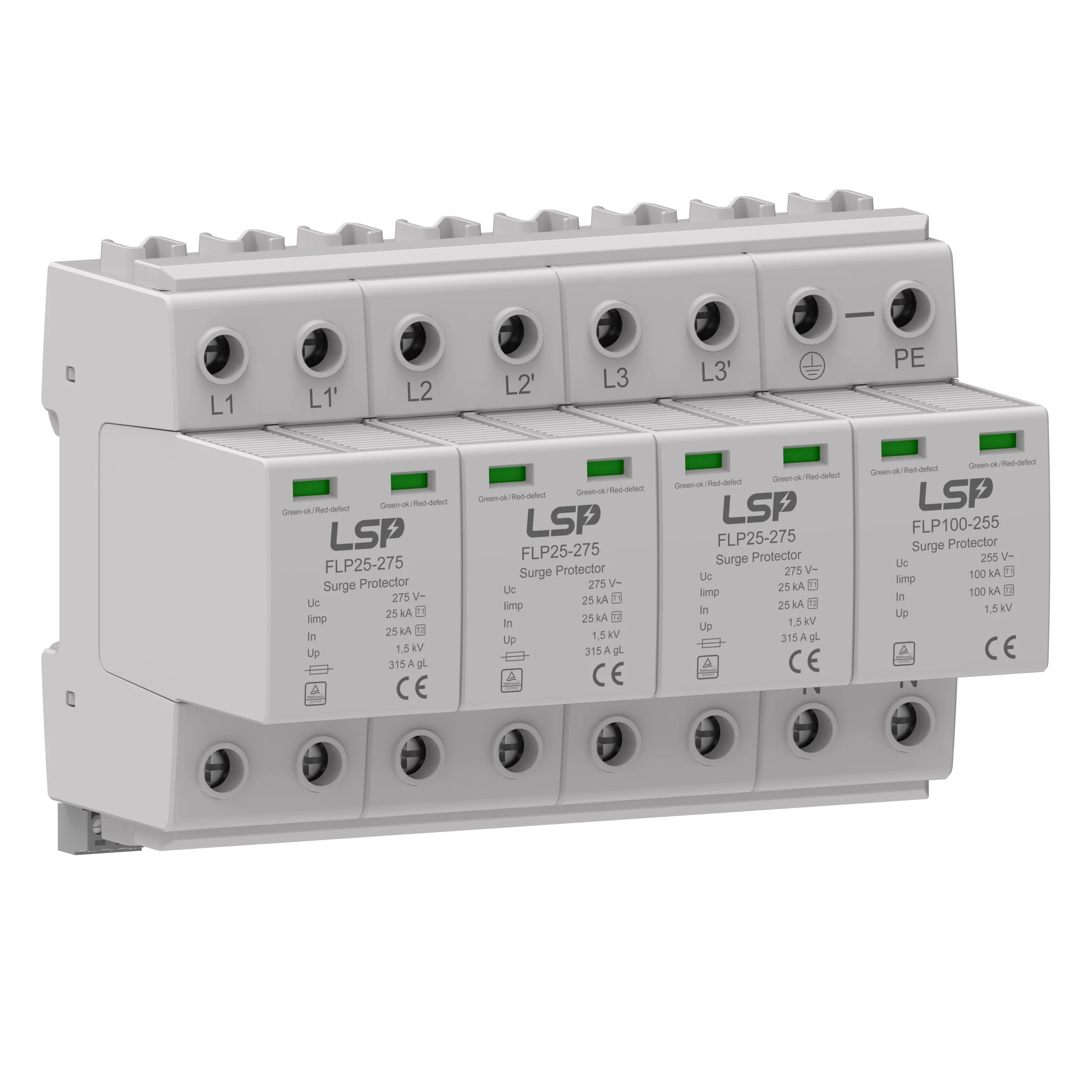
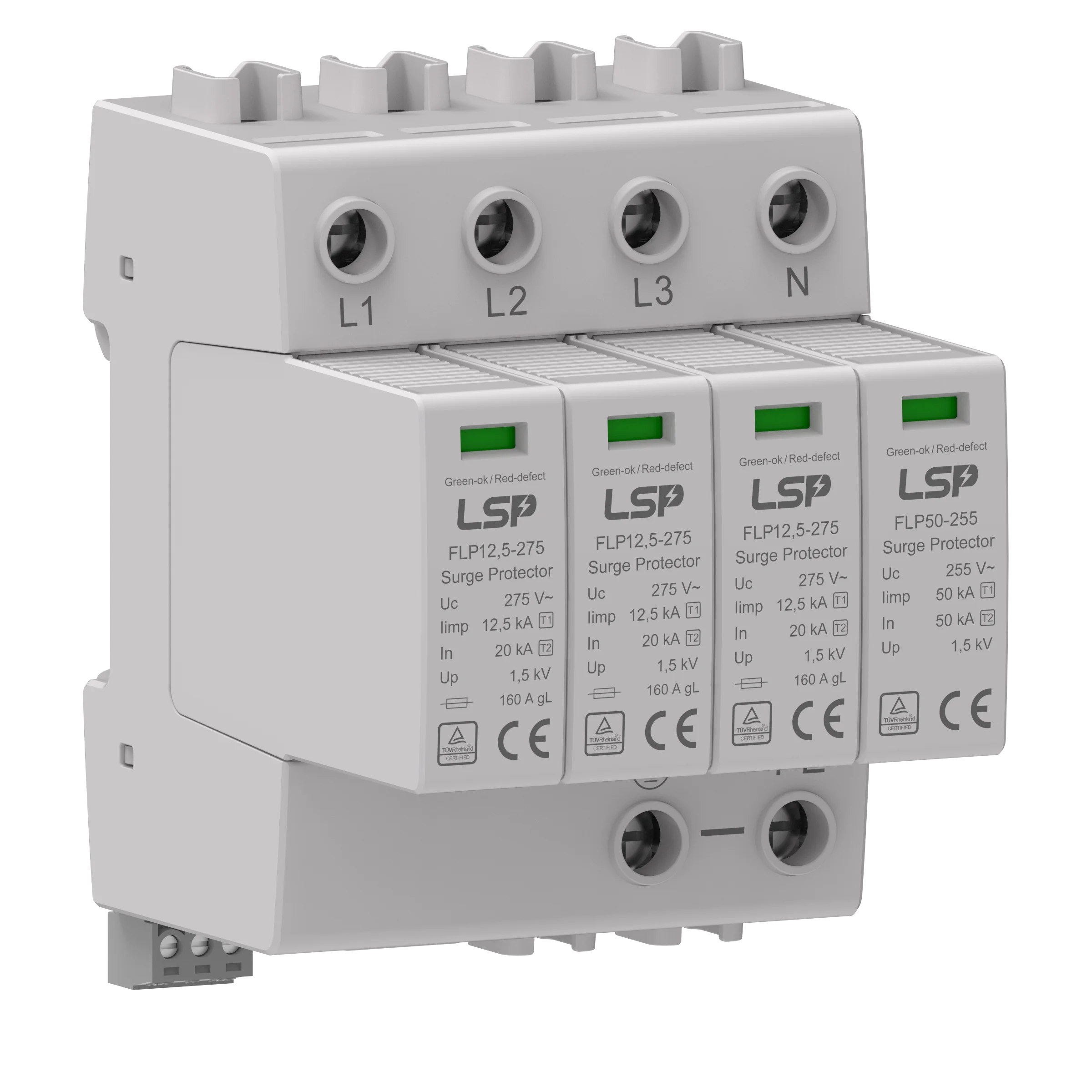
LSP’s DC SPDs are tested according to IEC 61643-31 and have been further optimized and field-tested for use in BESS DC applications. FLP-PV and SLP-PV products are all relevant for use and complementary to this application.
FLP-PV and SLP-PV are DIN rail mountable SPDs suitable for DC applications. These products are dedicated for use in smaller-sized BESS and rely on additional backup fuses.
Electrical design for a Battery Energy Storage System (BESS) container involves planning and specifying the components, wiring, and protection measures required for a safe and efficient operation. Key elements of electrical design include:
Solar power is becoming the go-to option for people across the world to meet their energy needs.
Why?
Today, the primary objective when it comes to generating power is sustainability. As a result, corporations, governments, and individuals are investing in renewable energy products to gradually shift from electricity generated by fossil fuels to being more energy-efficient, especially with climate change looming around the corner.
To meet the growing need for renewable energy products, we even released our line-up of solar PV products designed to meet the highest standards and provide customers with clean energy that they can count on.
While solar energy is the most viable renewable energy technology for the masses, it is by no means the only solution. Sustainable energy products such as hydraulic power, hydrogen-based fuels, atomic energy, and wind turbines are other examples of clean energy solutions.
But, all these investments in renewable technology systems could fail before the energy transition happens.
Why?
Even the slightest voltage spike can damage every electronic device drawing power from a solar panel array if it has no surge protection. This is aside from the fact that any energy-saving investment you make would be rendered useless without lightning protection since lightning is one of the main reasons solar panels malfunction.
Let’s dive into that a bit further.
Surge protection is a small part of an overall solar panel array installation; yet, it is an integral component that can’t be ignored. Like every other electrical device out there, solar panels are prone to sudden voltage increases that can damage their internal components.
This can often be attributed to lightning storms since solar panels are exposed and found on roofs, fields, or other isolated areas, making them prime targets due to their expansive size and metallic components.
Lightning poses significant risks of complete or partial destruction to solar farms either immediately from a direct strike or results in degenerative damage from an indirect strike.
Over-voltages can impact a solar panel system installation in different ways:
When lightning strikes a solar panel array, it causes an induced transient current within the system’s wire loops that leads to the failure of the insulation, panels, inverter, and communication equipment. Other components within the solar power system, such as the combiner box and MPPT (maximum power point tracker device), have the highest chances of failure.
Some solar PV systems might withstand physical or circuit damage to their panels; however, their circuit controls and energy storage devices will be instantly unusable after a lightning strike.
A surge protection network should be installed throughout a solar power system’s DC and AC power distribution network to safeguard critical circuits. The overall number of SPDs needed in a solar PV system varies depending on the distance between panels and inverter.
We recommend the installation of SPDs on DC inputs and AC outputs of a solar PV system’s inverters while grounding both positive and negative DC lines. Combiner circuits, control circuits, monitoring systems, and tracking systems must also be protected to prevent electrical interference and data loss.
Surge protection is a necessary component in any electrical installation, but by no means does it replace a proper lightning protection solution.
If you want to protect your investment, surge protection is not an option, it is a necessity, but if you want total protection and peace of mind, a lightning protection system can make the difference between the success and failure of large-scale solar power installations.
A lightning protection system not only protects the solar PV system but also provides reliable protection to your entire property and assets while safely diverting transient currents to the ground.
A simplified way to look at lightning protection vs surge protection is to view surge protection as the second line of defence against indirect lightning strikes.
In contrast, a complete lightning protection system that includes air terminals (lightning rods), down conductors, surge protectors, equipotential bonding, and an earthing system is the first line of defence against a direct lightning strike.
Suppose you want your solar power system to serve you continuously. In that case, it is imperative to understand that even the most advanced technologies have their limitations, which is why you need to have all your bases covered and be one step ahead by getting surge protection.
You must keep in mind that solar contractors may not be aware if they’re installing a solar PV system in an area prone to lightning strikes, not to mention that surge protection is generally not included during the installation of a solar system.
So, while you might already have a solar power system working correctly, that doesn’t mean that you have surge protection, which means that the fate of your electronics is entirely up to chance.
Your contractor might have even told you that your solar power system doesn’t need SPDs since your property already has surge protection – which would sound great in theory to reduce your costs. But, unfortunately, what it means is that you’re leaving your solar panels as sitting ducks once the next storm brews up.
Several billion lightning flashes come down in the world each year. In Germany alone, more than 2 million lightning events are recorded annually and the tendency is rising. If lightning strikes in the direct vicinity, it damages buildings and the infrastructure: Lightning strikes can cause fires or surge damage to electrical devices and systems. The latter also applies to lightning strikes up to 2 km away. The switching of a battery storage system or of a transformer in the grid may cause switching over-voltages and damage. It often takes only very small surges to damage electronic equipment.
Power storage systems are one of the key technologies of the energy revolution as they make it possible to store locally produced electricity on-site. The container battery storage systems store the power generated, e.g., by photovoltaic systems and wind turbines, and feed it back on demand. Thanks to decentral storage, they also reinforce network stability and can be used by the network operator to provide balanced power. The constantly increasing proportion of renewable energies leads to an increase in the number of grid-connected storage systems required.
Correspondingly, this increases the efficiency of renewable energies. The implementation of inverters with mains filters improves the voltage quality. In addition, battery storage for the power grid forms the basis for energy management (so-called “peak shaving”).
In order to provide optimum protection for the high-end electronics in storage containers, one needs a comprehensive lightning and surge protection system. Even more so, in view of the fact that the installation location and the operating conditions may vary considerably due to the mobile nature of the containers and their planned worldwide installation. The greatest danger for battery storage systems is lightning discharge. The resulting overvoltage far exceeds the dielectric strength of the electronic components in the storage system.
In addition, network-related voltage peaks, e.g., from switching operations or earth and short circuits must be considered a potential threat. The result is defective electronic components, e.g., information and communication technology and defective inverters or battery units. In the case of a direct strike, the metal roof may also be perforated resulting in water damage when it rains.
The constant availability of these storage systems is also a key issue. As damage leads to serious economic consequences and expensive maintenance and repair work, it is important to make provisions for a reliable lightning and surge protection concept.
The standard series IEC 60364 comprises installation standards and is therefore applicable to fixed installations. Permanently wired, non-mobile battery storage systems fall under the scope of IEC 60364.
IEC 60364-4-44 deals with the protection of electrical systems in case of transient over-voltages resulting from atmospheric influences transmitted via the supply network, including direct lightning strikes in the supply lines and transient over-voltages caused by switching operations.
It provides conclusions as to whether surge protective measures are required, assesses the risk of the location, defines surge protection categories and the correspondingly required rated impulse withstand voltage levels of the equipment, and defines whether additional surge protective devices are necessary. It also considers the required availability of the system. A risk analysis according to IEC 62305-2 is carried out to determine which external lightning protection measures are required, for example, which class of LPS needs to be considered in the planning and implemented in the lightning protection concept. If, for example, the risk analysis reveals the necessity for a lightning protection system of class 3 of LPS, IEC 62305-3 must be followed.
The German rule of application VDE-AR-E 2510-2 “Stationary battery energy storage systems for connection to the low-voltage- age network” also stipulates that provisions should be made for lightning and surge protection measures in the connection concept. If lighting and surge protection measures are implemented in compliance with IEC 60364-4-44 and IEC 62305, they should be installed in accordance with IEC 60364-5-53.
A direct strike in the battery energy storage system or in the supply line is characterized by lightning current with the im- pulse waveform 10/350 μs. Distant lightning strikes or so-called indirect lightning strikes lead to conducted partial lightning currents (impulse waveform 10/350 μs) in the supply lines, or also to induced / capacitive couplings (impulse 8/20 μs) in the electronic components of the storage system itself (so-called LEMP = Lightning ElectroMagnetic Pulse) (Figure 1). In addition, over-voltages can be caused by switching operations, earth and short circuits or the tripping of fuses (so-called SEMP = Switching ElectroMagnetic Pulse).
If PV power stations are equipped with a battery storage system, the electronic equipment, battery and inverter need to be protected against surges.
Figure 2 shows a PV storage system (container construction) that discharges the direct lightning strike to the soil via the metal housing of the container. To prevent a direct strike from melting holes in the metal roof, the four corners are fitted with air-termination tips as defined strike points. The earthing system illustrated consists of a 30 x 3.5 mm flat strip or, alternatively, a round wire with a diameter of 10 mm.
To ensure the durability and functionality of the earthing system, it is advisable to use a permanently corrosion resistant material such as stainless steel V4A (1.4404). This safeguards personal safety and the discharge of lighting currents to the earth for many years to come. The equipment inside the container is protected in a similar way to a Faraday cage, i.e., the separation distances to the electrical components inside must be kept. Suitable lightning current and surge arresters should be installed as closely as possible to where the mains supply lines enter the container in order to discharge any interference impulse coupling via these copper-based lines.
family to protect the 230/400 V supply line. This is a prewired, modular type 1 and 2 combined lightning current and surge arrester, based purely on spark gap technology with a discharge capacity of up to 100 kA (10/350 μs) which reliably protects terminal devices due to its excellent protection level and energy absorbing capacity.
When fitted with air-termination devices, the DC connection lines of a PV module must be protected by a type 1 surge arrester especially designed for use in photovoltaic systems, such as the FLP-PV1500G type 1 + 2 DC surge protective device.
If battery storage systems for the power grid have a concrete construction, is often impossible, or at least very difficult, to maintain separation distances to the external lightning protection system. This problem can be solved by installing high-voltage resistant insulated conductors, so-called HVI conductors.
In this way, one can prevent dangerous flashovers from the external lightning protection system to conductive parts such as supply lines. If the batteries and inverters are in separate containers, in the event of direct and nearby lightning strikes galvanic lightning currents are coupled in the connecting cables.
To prevent this from happening, an earthing conductor must be laid above the cables to include them in the protected volume. It is therefore enough to connect the cables on both sides to type 2 surge arresters. These are specially constructed for application in DC circuits and include a high-capacity DC switching device to prevent fire damage due to DC switching arcs.
Selection of lightning and surge protective devices When selecting appropriate lightning current and surge protective devices, many things play an important role in addition to details about the location: information on the local system configuration, the system voltage and the nominal current of the relevant interfaces.
Managing new challenges in terms of power protection, switching and conversion in Energy Storage Systems
Renewable energy sources, such as solar or wind, call for more flexible energy systems to ensure that variable sources are integrated in an efficient and reliable way.
Energy storage systems, and in particular batteries, are emerging as one of the potential solutions to increase system flexibility, due to their unique capability to quickly absorb, hold and then reinject electricity.
New challenges are at the horizon and market needs, technologies and solutions for power protection, switching and conversion in energy storage systems are rapidly evolving.
LSP’s reliable surge protection devices (SPDs) are designed to meet the protection needs of installations against lightning and surges. Contact our Experts!
It could be considered to use the existing AC power SPD overload protection fuse upstream as protection of the SPD.
Copyright © 2010-2024 Wenzhou Arrester Electric Co., Ltd. All Rights Reserved. Privacy Policy


