


Homepage » Surge Protection for CNC Machine, VFD and PLC
Created by: Glen Zhu | Updated Date: September 13rd, 2023

CNC stands for computer numerical control, which is the automated control of machining instruments like drills, lathes, mills, and 3D printers using a computer.
Depending upon its’ application, CNC machines have different types of electronics ranging from – dedicated electronics /PLCs / Display units with or without touch screens, interface to PC etc.
Failures in CNC machines happen due to two important disturbances (variables present) in low-voltage network steady-state errors and transient errors.
Steady state errors mainly comprise of over voltage which lasts several cycles (swell), harmonics, RFI/EMI effects, etc.
Transient errors comprise of transient over-voltages i.e, Lightning surges and switching surges due to operations like welding, capacitor bank switching, etc.
Direct lightning strike. It is very rare because CNC machines are installed inside a structure & are fed by sub-distribution boards, whereas only the main DB bears the brunt of direct lightning strikes in lightning-prone areas. The other reason, often unnoticed is, inductive lightning strike. In this case, the lightning current is carried by all types of cables except optic fiber cables.
Before discussing SPDs, let us first understand what is surge and how it is going to affect our CNC machines so that it will be easier to install appropriate SPDs for the protection of CNC machines.
Put in simple terms, a surge is a sudden increase in current and voltage for a short period (a duration of 350 microseconds during lightning and 20 microseconds during switching). There are various sources of surges.
Artificial transient surges occur due to brownouts, blackouts, capacitor switching, frequent switching on/off of heavy-duty equipment, welding, electrostatic discharge, etc. Mother Nature generates two types of surges: direct lightning strikes, which are extremely rare, and distant lightning-induced indirect surges, which are common.

Many feel that unless they see a charred PCB they won’t accept that the problem is due to lightning /switching surge effects. The more common problem we encounter in normal plant life is corruption of EPROM (Erasable Programmable Read-only memory).
This is visible from the sudden junk data appearing in the MMI (Man Machine Interface) panel. In general, it is not a common practice to put that loop of PLC or DCS in manual mode, remove the corrupted EPROM , erase it in UV eraser, reprogram it and put it back into operation as this is a long drawn & time-consuming process, resulting in production loss. . If we examine why such corruption of EPROM suddenly takes place, the reason will be surges.
Because, while programming is taking place, a voltage higher than the normal working voltage is applied to specific EPROM pins (so that EPROM understands that it is in programming mode and not in normal operating mode).
During a surge, the same thing happens. Because a sudden high voltage appears in the pins of the IC, it believes it is in programming mode and the ones because the extra high voltage appears in the pins.
This is the cause of EPROM collection. As a result, the intensity of surges is solely responsible for the failure or corruption of programs in the CNC machine. CNC machines’ SMDs and electronic equipment are designed to endure a minor increase in voltage levels that falls well within the tolerance limit.
This is known as equipment withstanding voltage, and it is typically 1000 V AC RMS for 1 minute for PLC and electronic equipment with a 230V AC input power supply voltage. If a surge of this magnitude occurs, nothing happens to the equipment. These levels are greater than the standard tolerance limit; over time, they are high enough to permanently fail the equipment.
Generally, we feel that SPDs are not required as we have a number of (other existing) protection arrangements viz. external lightning arrestor, MCB/ MCCB, good earthing, bonding, shielding, isolation transformers, UPS, Intrinsically safe barriers, isolators.
Unfortunately, the purposes of all these equipment are for different reasons altogether and not for protecting the equipment from transient surges. Let us analyze the scope of each one of them.
Hence SPDs are the only protectors for the CNC machines against transient surges. Now, we can discuss the proper selection and installation of SPD for trouble-free operation of a CNC machine.
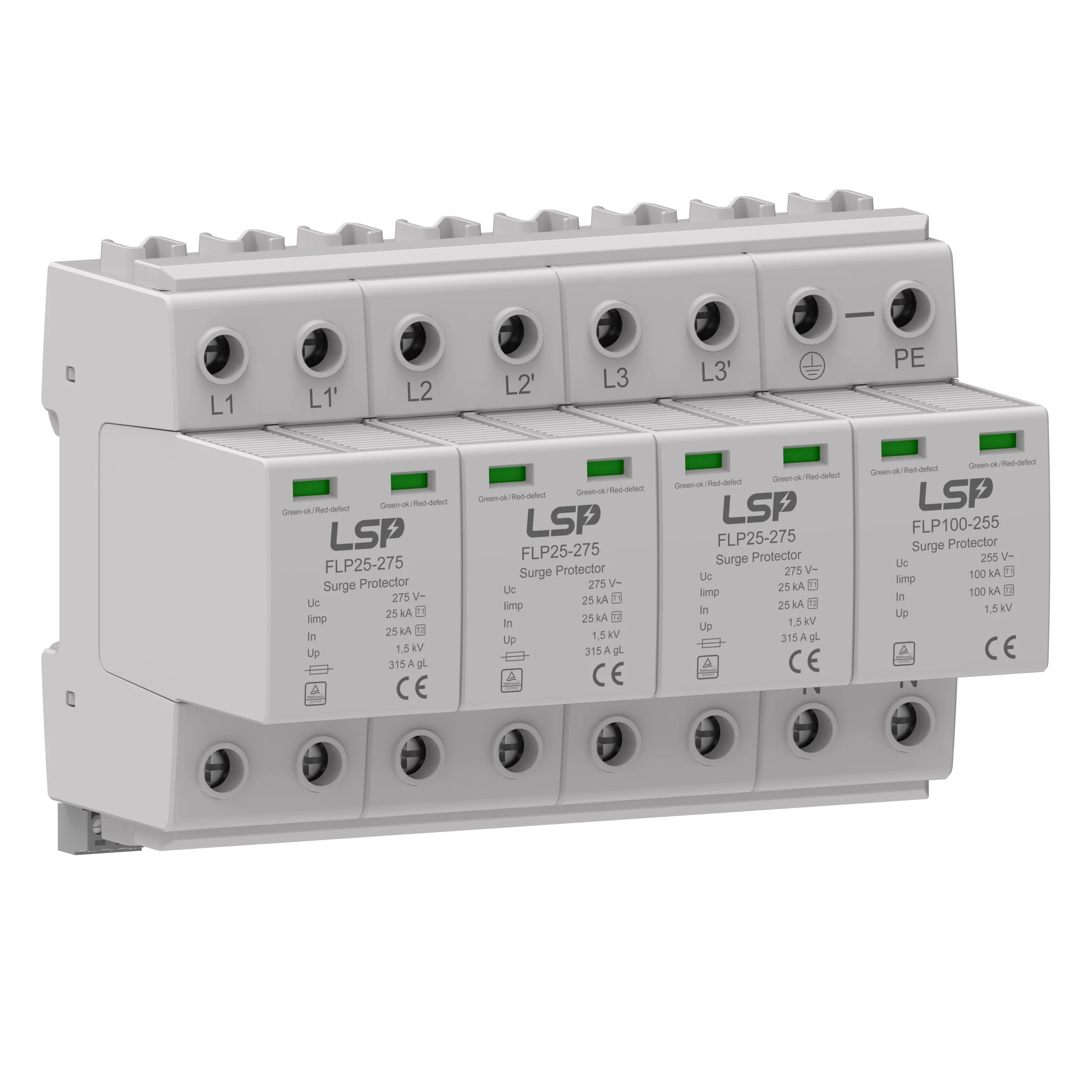
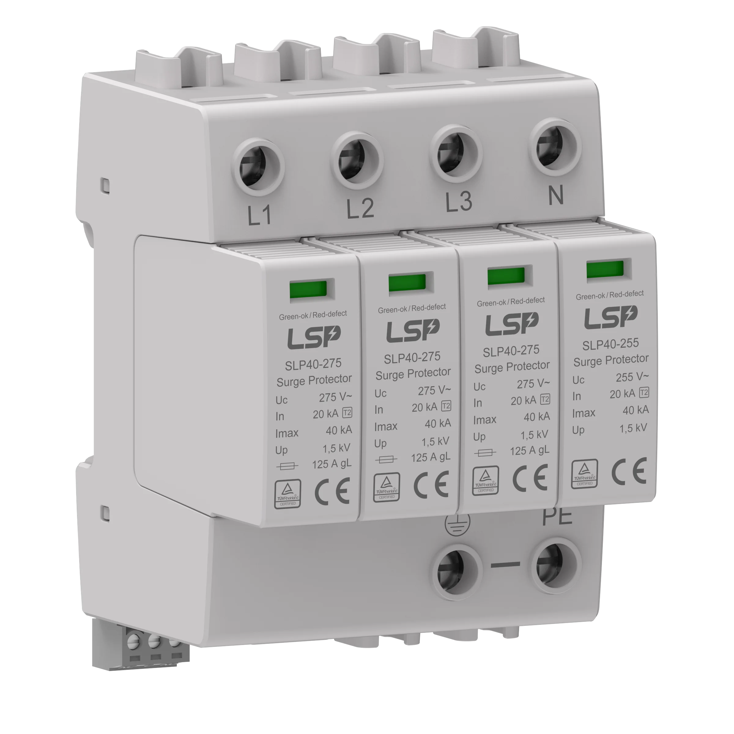
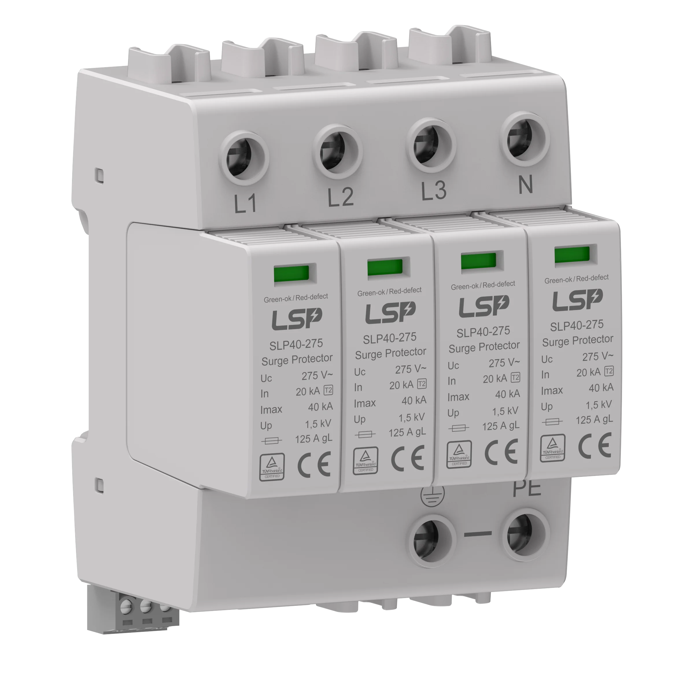
Depending on the incoming supply of CNC machine i.e., 3 phase with neutral or without neutral, SPDs shall be installed with potential free contact, thermal disconnecter, including base element & pluggable arresters to be connected between Phase to Neutral (3 nos. for 3 phase to neutral ) and between neutral to protective earth. SPDs for three-phase power supply (L-N), (N-E) at local or sub-distribution board or branch panel should have l MOVs for L-N (WITH MCOV of 275 V to take care of power supply fluctuations & SPARK GAP for N-E. The requirement class is Class I + II as per IEC 61643-11. This is the first level of defense.
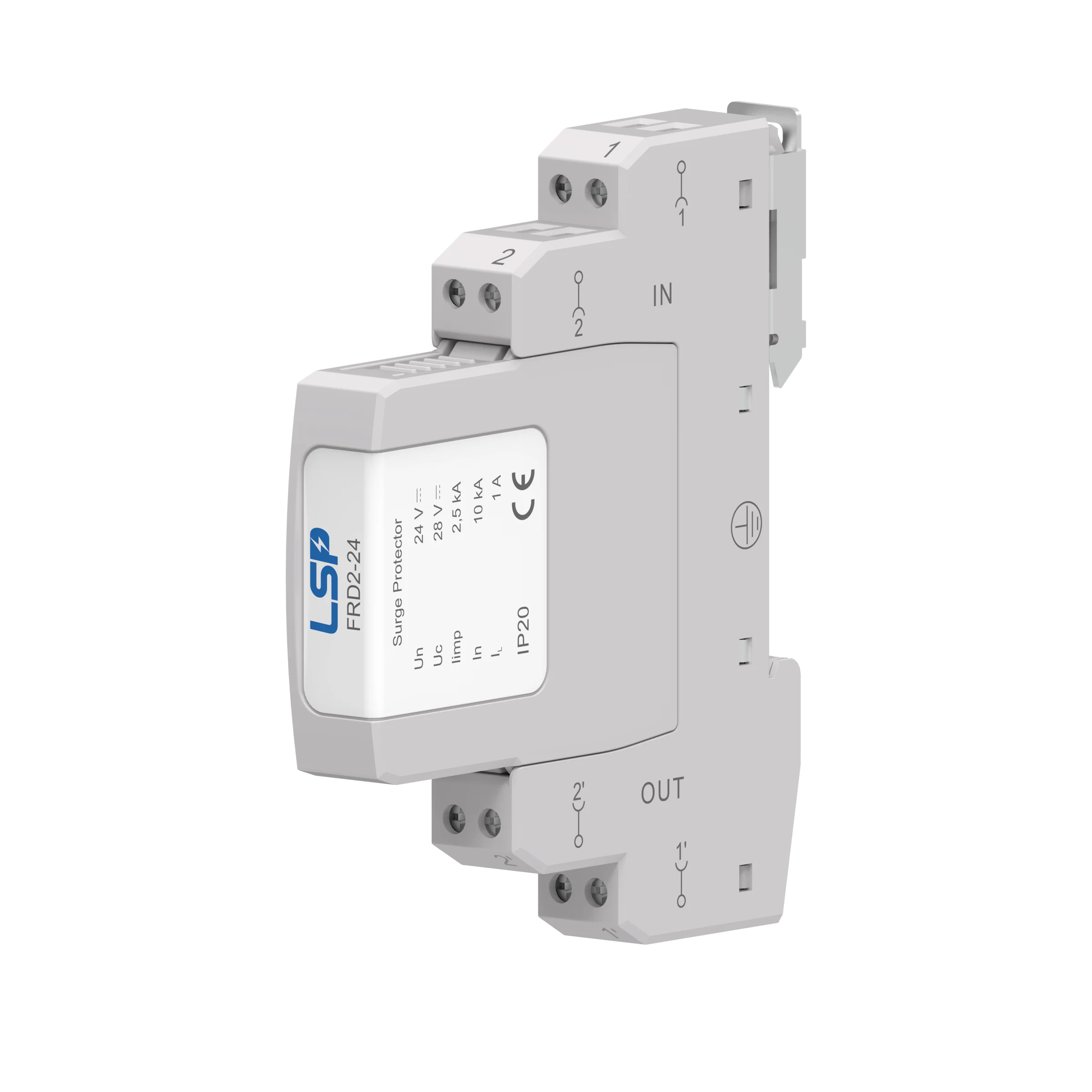
For MMI to have a 24V DC power supply or PLC with DI/DO, suitable SPDs need to be selected, apart from having Class I + II SPD in the main distribution board.
We list the machines that need surge protection as below:
Types of machines |
|
Machine Tools: | Metal Cutting Metal Forming |
Plastics Machinery: | Injection molding machines Extrusion machinery Blow molding machines Specialized processing machines Thermostat molding machines Size reduction equipment |
Wood Machinery: | Woodworking machinery Laminating machinery Sawmill machinery |
Material-Handling Machinery: | Industrial robots Transfer machines Sortation machines |
Inspection/Testing Machines: | Coordinate measuring machines In-process gauging machines |
Packaging Machines: | Carton-strapping machines Drum-filling machines Palletizing machines |
Surge protection and lightning for CNC (Computer Numeric Control) equipment is of paramount importance in safeguarding these intricate and valuable machines from the destructive effects of transients and surges. CNC machinery, encompassing a wide range from lathes and milling machines to laser systems and 3D printers, holds a pivotal role in modern manufacturing processes. These machines are susceptible to voltage fluctuations, transient spikes, and electrical surges that can result from various sources including lightning strikes, power grid fluctuations, or equipment switching.
Implementing surge protection helps shield CNC machines from voltage anomalies, preventing potentially catastrophic damage that can lead to downtime, material loss, and subsequent financial setbacks. A surge event can disrupt operations, degrade the accuracy and precision of these machines, cause glitches and lockups, and even lead to irreversible damage, necessitating expensive repairs or replacements.

Surge protection devices can be used to help protect a VFD from voltage transients, spikes, and power surges which are commonly caused by lightning strikes.
A Variable Frequency Drive (VFD) also known as a Variable Speed Drive (VSD) is the main component of any moving part in the electrical equipment.
This device allows for the control of speed to almost any electrical motor, which otherwise would always be a constant speed. This is done by adjusting the output frequency to the electrical engines.
VFDs are found in a multitude of applications: Pump panels, HVAC compressors, conveyors, CNC machines, blowers, machine tool speed, etc. Therefore, they are found across multiple industries, such as Water Waste Treatment, Oil & Gas, and Industrial Machinery.
A frequency converter typically consists of a rectifier, D.C. link, inverter and control electronics (Figure 1).

Figure 1 – Basic principle of a frequency converter
At the inverter input, a single-phase A.C. voltage or three-phase line-to-line A.C. voltage is converted into a pulsating D.C. voltage and is fed into the D.C. link which also serves as an energy storage system (buffer).
Capacitors in the D.C. link and earthed L-C sections in the mains filter can cause problems with upstream residual current protective devices (RCDs). These problems are often incorrectly associated with surge arresters. They are, however, caused by short-time fault currents of the frequency converter which are sufficiently high to trip sensitive RCDs. This can be prevented by using a surge-proof RCD circuit breaker which is available with a discharge capacity of 3 kA (8/20 µs) and higher for a tripping current I∆n = 30 mA.
The inverter provides a pulsed output voltage via the control electronics. The higher the pulse frequency of the control electronics for pulse width modulation, the more similar is the output voltage to a sinusoidal curve. However, with each pulse a voltage peak occurs that is superimposed on the fundamental wave. This voltage peak reaches values of more than 1200 V (depending on the frequency converter). The better the simulation of the sinusoidal curve, the better the run and control performance of the motor. This, however, means that voltage peaks occur more frequently at the output of the frequency converter.
In order to pick the correct surge arrester for your frequency converter, the maximum continuous operating voltage Uc must be taken into account which specifies the maximum permissible operating voltage a surge protective device may be connected to. Owing to the voltage peaks that occur during the operation of frequency converters, arresters with a high Uc value must be used to avoid “artificial aging” due to the heating of the surge arrester under “normal” operation conditions and the associated voltage peaks.
Heating of surge arresters can lead to shorter service life and a disconnection of the surge arrester from the installation it is supposed to protect.
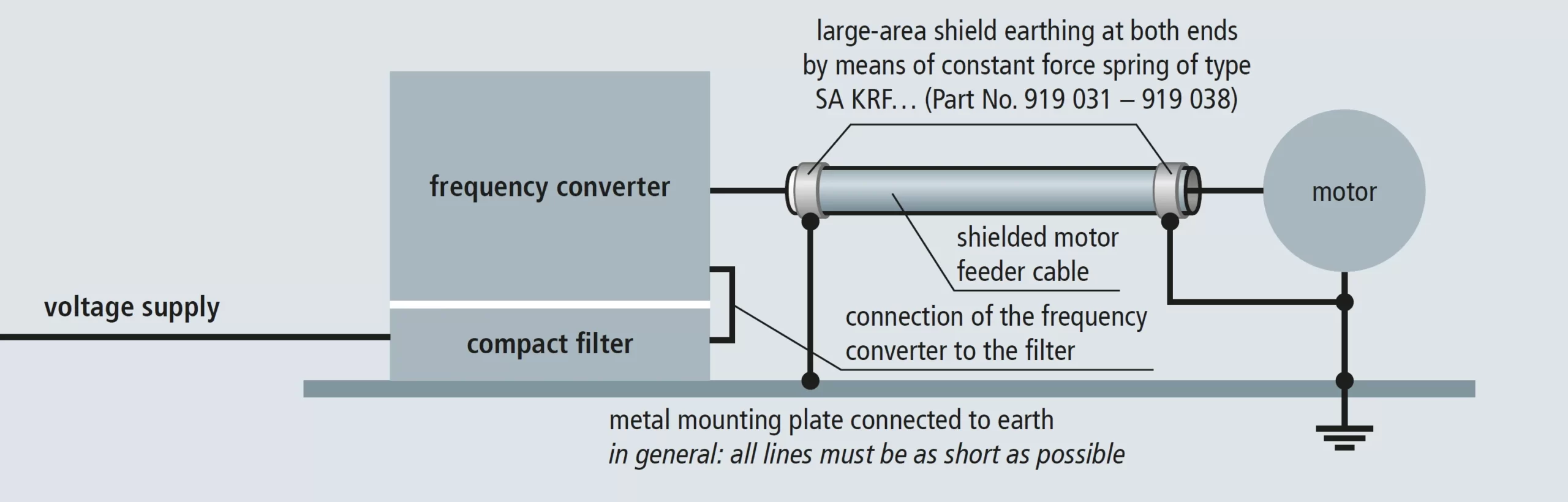
Figure 2 – EMC-compatible shield connection of the motor feeder cable
The high pulse frequency at the output of the frequency converter causes field-based interference. To avoid that other systems are interfered with, the motor feeder cable must be shielded. The shield of the motor feeder cable must be earthed on both ends, namely at the frequency converter and at the motor.
To this end, large-area contact with the shield must be provided, preferably by constant force springs (Figure 2), to fulfill EMC requirements. Intermeshed earth-termination systems, namely the connection of the earth-termination system of the frequency converter to that of the drive motor, reduce potential differences between the different parts of the installation, thus preventing equalizing currents from flowing through the shield.
When integrating a frequency converter in the building automation, all evaluation and communication interfaces must be protected by surge protective devices to prevent surge-related system failure. Figure 3 shows an example of the controller interface 4 – 20 mA.
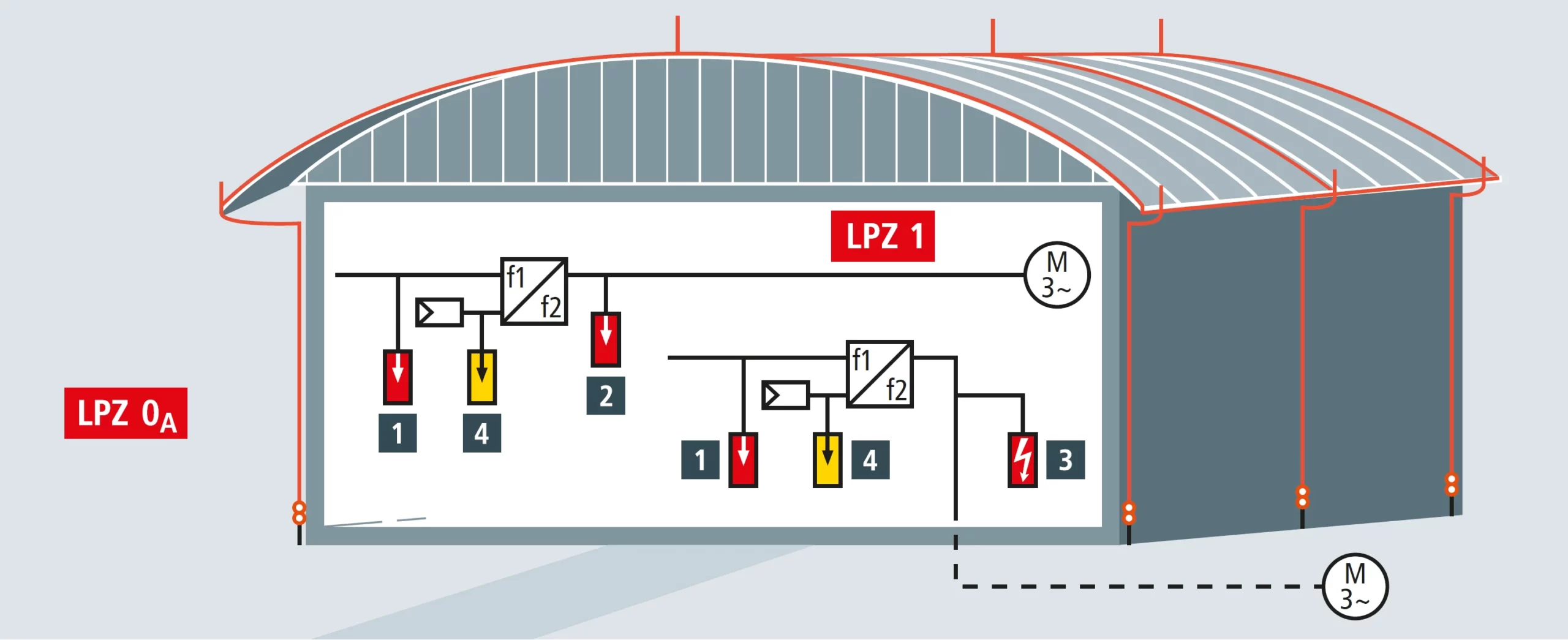
Figure 3 – Frequency converter with drives in LPZ 0A and LPZ 1
Over-voltages can be long-term, temporary, or just a short transient (surge). Surge or spike is a short-term high voltage typically much more than 110% of the nominal voltage. Transient overvoltage can have an atmospheric origin (lightning strike) or a switching transient in the grid. A popular and effective protection against transient over-voltages is the use of surge arresters.
These devices have highly non-linear impedance as a function of applied voltage. In normal operation (below the threshold voltage) the surge arresters have very high impedance and only negligible leakage current is flowing through the arrester. When the voltage exceeds the threshold the impedance drastically drops and the surge arrester creates a path for the surge current. Surge arresters are typically applied phase to ground, between phases or a combination of both.

Figure 4 – Surge arresters installed phase to ground and phase to phase.webp
The spelling can be both surge arrester or surge arrestor. Another naming is surge protection device (SPD).
Surge arresters are commonly used to protect electric equipment against excessive over-voltages. At the same time, many voltage source inverters produce non-sinusoidal voltages that stress the machine insulation. Thus, one could ask whether surge arresters are suitable means to protect the motors supplied from variable frequency drives?
The short answer is ‘No’. Most drive systems with a voltage source inverter will not benefit from surge arresters. In opposite, the installation of surge arresters would likely cause an

Figure 5 – Are surge arresters suitable for protection of VFD fed motors
Sophisticated and highly susceptible microprocessor-based electronics and data communication networks are integrated across every sector of today’s fast-paced business world. Preserving these mission-critical systems from the damages of surges, spikes, and transients ensures that these systems are protected from equipment destruction, disruption in service, and costly downtime. How to properly stage these SPDs can be as important as actually deciding to purchase them.
Overall, properly installed surge protective devices reduce the magnitude of random, high-energy, short-duration electrical power anomalies. These occurrences are typically caused by atmospheric phenomena (such as lightning strikes), utility switching, inductive loads, and internally generated over-voltages.
The use of various types of drives to control motors is widespread. The purpose of the drive is to increase the efficiency or to manage the speed of the motor being controlled. Through various processes and control mechanisms, the drive often reshapes the sinewave to provide a signal to the motor that allows for greater efficiency or varies the frequency of the signal to control the speed of the motor.
Due to the action of the drive, the power quality of the electrical environment can be compromised. That is, the drives can create voltage surges and harmonics on the system.
Applying surge protective devices (SPDs) to a drive system to mitigate the damage that can occur due to voltage surges while considering the effects of the harmonics on the surge protective device.

To aid in the description of the application of SPDs to a drive system, please refer to Figure. This figure illustrates a typical drive layout. The incoming power is usually delta configured (3 phases and ground).
Often the incoming voltage is 480 V, but other voltages may be used. The incoming power is usually stepped down to a lower voltage (typically 120 Vac) that provides power to the control circuit. The control circuit contains sensitive electronics. Once the power is acted upon by the drive the output is fed to the motor.
As noted, there are five opportunities for protecting the typical drive system–each are labeled with a circled number and are described below.
Protecting the drive input is an essential step in protecting the drive system. Protecting this location prevents surge damage due to events propagated on the electrical system from upstream sources, external events such as lightning and switching surges created by the utility, and the interaction of multiple drives on the same system.
At this location, a parallel connected, voltage responsive circuitry device is appropriate–one without frequency responsive circuitry. Frequency responsive circuitry is not recommended for this location since this location is typically more susceptible to impulse transients as opposed to ring wave transients.
The inverter input is one of the most sensitive and critical areas of the drive itself. It’s this location where care must be taken and a proper survey conducted. You may install a parallel connected, frequency responsive circuitry device provided you have confirmed no additional capacitors have been installed to mitigate harmonic currents within this drive.
If addition capacitors are installed, a parallel connected, voltage responsive circuitry device is appropriate at this location–one without frequency responsive circuitry. Frequency responsive circuitry would not be recommended for this location due to the high harmonic content that necessitated the installation of additional capacitors. Installation of frequency responsive circuitry devices at this location will lead to failure of the SPD.
The control circuit contains sensitive electronics that can be damaged by the environment created by the drive or by surges from external sources. Protection at this location is essential.
Since a step-down transformer isolates this circuit and feeds sensitive electronics, a series connected SPD with frequency responsive circuitry is recommended for this location.
Protecting the immediate drive output is recommended when the length of the connection between the drive and the motor is longer than 50 ft (15 m) or if the connection is routed along an external wall or outdoors.
One reason for protecting at the immediate output when the length of the connection to the motor is long is due to reflected waves that can occur as the signal (often higher frequency) from the output of the drive reaches the motor and is then reflect back and forth between the drive and the motor. This action can create “voltage piling” – the reflected voltage adds to the nominal voltage and other reflected waves. The SPD will aid in reducing the voltage peaks of the reflected waves.
Long lengths and those routed along external walls or doors can cause reflected waves. Reflected waves occur as the signal (often higher frequency) from the output drive reaches the mother and is reflected back and forth between the drive and the motor. this action creates “voltage piling.” The reflected voltage adds to the nominal voltage and other reflected waves. The SPD will aid in reducing the voltage peaks of the reflected waves.
More importantly, if the connection between the drive and the motor extends outdoors along a path that is exposed to the environment or close to the building’s steel structure, protection at this location is essential to diminish the effects of direct lightning or induced voltage surges due to nearby lightning. These surges can cause damage to the drive, even if protection is provided at the motor input.
At this location, a parallel connected, voltage responsive circuitry device is appropriate–one without frequency responsive circuitry. Frequency responsive circuitry is not recommended for this location due to the high harmonic content of the signal due to the normal operation of the drive. Installation of frequency responsive circuitry devices at this location will lead to failure of the SPD. Utilizing a voltage responsive circuitry device at this location will eliminate this possibility.
Protecting the motor input is an essential step in protecting the drive system. Providing protection at this location prevents surge damage due to events propagated from the drive output to the motor input. Protecting this location aids in extending the life of the motor as the SPD helps to prevent damage to the windings and bearings of the motor due to surges.
Further, if the connection between the drive and the motor extends outdoors along a path that is exposed to the environment or close to the building’s steel structure, protection at this location is important to diminish the effects of direct lightning or induced voltage surges due to nearby lightning. These surges can cause damage to the motor, even if protection is provided at the drive output.
At this location, a parallel connected, voltage responsive circuitry device without frequency responsive circuitry is appropriate. Frequency responsive circuitry is not recommended for this location due to the high harmonic content of the signal due to the normal operation of the drive. Installation of frequency responsive circuitry devices at this location will lead to failure of the SPD. Utilizing a voltage responsive circuitry device at this location will eliminate this possibility.
As any other electric system, VFD systems need to be protected against surges and overvoltage transients. These surges can come from the utility side or be generated by the drive itself.
Typically, the surges that come from the power system are less frequent and have higher energy and amplitude. These surges could be lightning surges, or the switching surges from the power system.
In addition to those surges, operation of the converter/inverter also can create over-voltages that can be detrimental to the sensitive electronic circuits. An effective surge protection of a drive system should protect the power electronic switches and control circuit as well as the motor.
In a typical drive system, there are five points to place surge protection devices, shown in Figure 6.

Figure 6 – SPDs used in these locations might use protective devices
The SPDs used in these locations might use protective devices with different technologies. In commercial products, some SPDs might be integrated with other products, such as filters to provide protection against poor power quality or high harmonic distortion.
Advanced Random Rotary Knife with Cam Blend | Air Compressor |
Blister pack Thermoformer | Cartoner |
Centrifuge | Conveyor |
Crane/Hoist | Dynamometer |
Elevators and Escalators | Extrusion |
Fans/Blowers | Feed To Length |
General Machinery | HVAC |
Irrigation | Labeler |
Laundry | Linear Flying Shear |
Machine Tool | Mixer |
Packaging | Palletizer |
Precision Grinding | Pump |
Punch Press | Rotary Knife |
Rotary Placer | Screw Feeder |
Rotary Table Indexer | Synch-Belt |
Textile | Winding |
LSP’s reliable surge protection devices (SPDs) are designed to meet the protection needs of installations against lightning and surges. Contact our Experts!
Copyright © 2010-2024 Wenzhou Arrester Electric Co., Ltd. All Rights Reserved. Privacy Policy


