


Homepage » Lightning and Surge Protection for Wind Turbines
Created by: Glen Zhu | Updated Date: October 6th, 2023

To benefit from better wind conditions, wind turbines are typically placed in exposed regions.
However, they are far more likely to be directly struck by lightning than conventional installations due to exposed location and height. These events caused by lightning strikes could seriously damage sensitive electronic equipment within the wind turbine system
Windmill generators are equipment especially exposed to the risks of lightning and transitory over-voltages: due to their height and to their location on high or/and isolated spots, the probability of direct lightning strikes is much higher than for traditional installations.
Wind turbines are generally located in exposed areas for better wind conditions, onshore wind turbines are usually located at prominent terrain like mountains regions and offshore located at coastwise, by the effect of location and the height of structure, wind turbines have higher annual estimated number of lightning strikes according to lightning location system.
All types of lightning flashes generate lightning electromagnetic impulses (LEMP) on the connecting cables between the equipment, and the damage is mostly caused by insufficient impulse withstand voltage level of equipment components.
LEMP is the main threat leads to malfunction and failure for electrical and electronic systems, now the most efficient measures to reduce loss towards LEMP is using coordinated SPD protection consists of a set of SPDs properly selected.
Surge protectors are crucial parts intended to direct extra energy produced by voltage spikes away from vital wind turbine system components.
LSP has designed a complete range of AC and Telecom-Data surge protectors for Wind turbine applications that are compliant with the IEC 61400 et IEC 62305 standards.
Wind turbines are usually located in open areas with excellent wind resources. For example, onshore wind power generation is located in protruding terrain such as ridges, while offshore wind power generation is usually located in areas with high ground flash density near coastlines. At the same time, blades of the wind turbines can induce and trigger upward leaders and actively connect with downward leaders in electrostatic fields of thunderstorms, which greatly increases the probability of lightning striking the blades. For this reason, the estimated annual average number of lightning strikes on wind turbines is much higher here than in other areas.
Lightning strikes on a wind turbine may cause blade ablation, a failure of an electrical and control system, and other phenomena. There are many such cases. The yield loss caused by wind turbine maintenance and downtime is very large. For an offshore wind turbine, the maintenance costs are particularly high, and the maintenance period is long. As a result, a big indirect loss is brought by the halt.
Compared with direct lightning strikes, the indirect effect of lightning strikes, namely a lightning electromagnetic pulse (LEMP), is more risky to the electrical and control system of the wind turbine. The main reasons are as follows:
LEMP is currently the main threat for breakdowns and failures of the electrical and electronic system. At present, the most cost-effective and reasonable main measures are taken: installing a surge protective device (SPD), which discharges the energy matches with the endurance capability of the protected equipment and the immunity of the system, at the boundaries of the lightning protection zones or at the front end of the protected equipment.
The basic protection method of wind power generation needs to meet the requirements of the basic protection standards of the lightning protection industry: the international standard IEC 62305-1 to 4 and the national standard
The general and special requirements for wind power industry applications need to meet the requirements of standards IEC 61400-24, which provide requirements for protection of blades, other structural components, and the effects of direct and indirect lightning strike on the electrical and control system while putting forward a request for typical environmental effect factors that the SPD should be able to bear.
With regard to the performance and model selection requirements of the surge protection device, testing and model selection are required in accordance with SPD-related standards IEC 61643.
In accordance with IEC 62305, four lightning protection levels are formed, LPL I to IV. For each LPL, the maximum and minimum values of the lightning current parameters that can be protected are specified (see the table below). In accordance with the requirements of the wind power lightning protection standards IEC 61400-24, it is the most reasonable that the wind turbine set and the component system should be divided according to the highest lightning protection level LPLI (except for special requirements).
First positive return strike lightning current | Lightning Protection Level (LPL) | |||||
Current parameters | Symbol | Unit | 1 | 2 | 3 | 4 |
Peak current | I | kA | 200 | 150 | 100 | |
Impulse charge | QSHORT | C | 100 | 75 | 50 | |
Specific energy | W/R | MJ/Ω | 10 | 5.6 | 2.5 | |
Time paramerters | T1/T2 | μs/μs | 10/350 | |||
Defining reasonable lightning protection zones of the wind turbine is a prerequisite for effective surge protection. In general, protection measures, such as a lightning protection system (LPS), the shielding of the wire, and the installation of SPDs, are used to determine the lightning protection zones (LPZ). For details, see Chapter 8.3 of IEC 62305-1.
The following is a schematic diagram of division of the typical wind turbine into lightning protection zones.
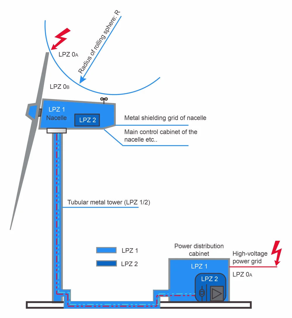
*Note: The locations of power distribution room/cabinets of wind turbines of different models vary. For example, the offshore wind power distribution cabinet is normally located inside the tower.
A tubular metal tower, which is used for a large wind turbine, can be regarded as an almost perfect Faraday cage, owning to its electromagnetic shielding effect. If the electrical connection between the tower and the nacelle is intact and safety grounding is done, the area inside the tower can be defined as LPZ 1 or even LPZ 2.
The nacelle with glass fiber metal grids has a shielding effect on an external electromagnetic field. The shielding effect is related to the size of the grids. The nacelle is generally defined as an LPZ 1 zone. A portion of lightning current may exist in the nacelle to flow through bearings so as to be discharged to the ground via an electric brush, so there may be a radiated electromagnetic field that cannot be shielded by the metal grids.
The transformer and the grid connection of onshore wind turbines is mostly arranged outside the tower and can be defined as an LPZ 1 zone. For offshore wind turbines, the transformer and the grid connection is normally located inside the tower and can be defined as an LPZ 2/3 zone.
The hub mostly consists of a hollow cast iron structure with multiple openings, it provides a magnetic shielding and should be defined as LPZ 1 zone. Inside the hub the pitch control system is located as well as different control system circuits leading to the nacelle.
The typical LPZ method is used for wind turbines to evaluate and determine the degree of influence of lightning strikes. Components like blades, machines, electrical and control systems can be built to endure this stress.
The test type, discharge capability and installation location of the SPD should be determined according to the influence characteristics of the electrical system at the boundaries of different protection zones. Examples of surge protection measures (SPM) of the electrical system at the boundaries of different protection zones are as follows:
In general, one of three different types of wind turbine sets is used in a wind energy generation system. A doubly-fed induction generator (DFIG), a direct drive generator (PMSG) and a medium-speed generator (a semi-direct drive generator).
Two main types of transient overvoltage may occur during the operation of the wind turbine:
As a switching device, IGBT is widely applied to converters. When the IGBT modulates and outputs PWM waves to a rotor, the voltage will produce recurring high peaks and transients (harmonics) of the gradient ascending time (du/dt). This harmonic interference will affect the insulation of the rotor generator and the normal operation of the SPD.
A converter at the bottom of the tower outputs pulse width modulation waves (PWM), and the distance of transmission of the pulse width modulation waves to a cable of the generator of the nacelle is long. Since long cables have distributed inductance and coupling capacitance, high-frequency overvoltage damped oscillation (harmonics) will be generated. The possible overvoltage characteristics of the wind turbine are as the standards (the table below). If the endurance capacity of the SPD does not meet the requirements of on-site working conditions, its life expectancy will be greatly reduced.
Typical voltage characteristics of rotor side of DFIG | |
maximum continuous operating voltage of the system (L-L) | 750V r.m.s. (±10%), 0~200Hz |
transient overvoltage repeatedly superimposed over the operating voltage L-PE | 1.7 kV |
transient overvoltage repeatedly superimposed over the operating voltage L-L | 2.95 kV |
The ascending gradient of repeatedly superimposed overvoltage waveforms | 1.4 kV/μs |
The switching frequency of the converter | 2000 Hz |
The high voltage ride-through characteristics given by the relevant standards and shown in the figure below will appear when the electrical system of the wind turbine operates. This type of temporary overvoltage (TOV) will appear in DFIG&PMSG, which may pose a threat to the safe operation of semiconductor equipment including a converter and the like.
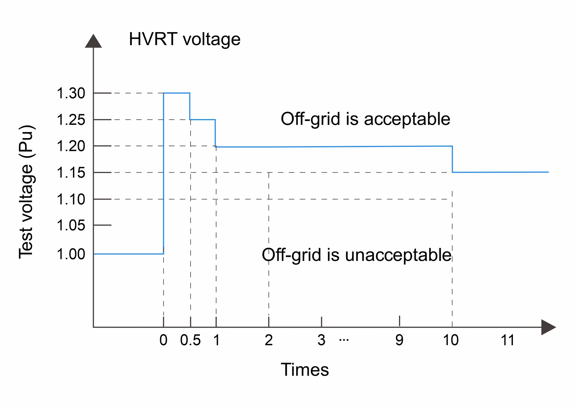
No. | Operating voltage | HVRT requirements | LSP model | SPD parameter |
1 | 400/690Vac | 400*1.1=440Vac continuous | SLP40-760/3S | UC=760Vac continuous |
2 | 400*1.3=520Vac 500ms | UT=1000Vac 5s withstand | ||
3 | 400*1.1=440Vac continuous | SLP40-760/3S+1-2600DC | UC=800Vac continuous | |
4 | 400*1.3=520Vac 500ms | UT=2200Vac 5s withstand | ||
5 | 230/400Vac | 230*1.1=253Vac continuous | SLP40-320/3S+1 | UC=320Vac continuous |
6 | 230*1.3=299Vac 500ms | UT=335Vac 5s withstand |
For the incoming line (there is a portion of intrusive lightning current on the line) connected to the LPZ 0A or LPZ 0B, AC ports and DC ports of electronic equipment such as the main control system, should be subjected to an immunity test in accordance with the standards IEC 61400-4-5 and IEC 60664-1, the communication port should be tested by reference to ITU-TK.21, K.20 and IEC 61400-4-5.
Temperature and humidity
LSP’s SPD temperature range: -40 °c to 85 °c (limit)
LSP’s SPD humidity range: 5% to 95 % (limit)
Vibration
LSP’s SPD vibration meets: IEC 61400-24 requirements
Salt spray
LSP’s SPD salt spray meets the requirements:
adopting the closed discharge technology being suitable for the marine salt spray environment
Mildew
LSP’s SPD meets the anti-mildew requirements: anti-mildew and antibacterial shell materials
Voltage Protection level – UP
The voltage protection level Up of the SPD used by the wind turbine should consider the rated impulse withstand voltage Uw of the protected equipment (as shown in the table above). If necessary, requirements for the immunity level of an SPD installation system of the wind turbine should be considered at the same time.
Maximum safe continuous operating voltage – UC
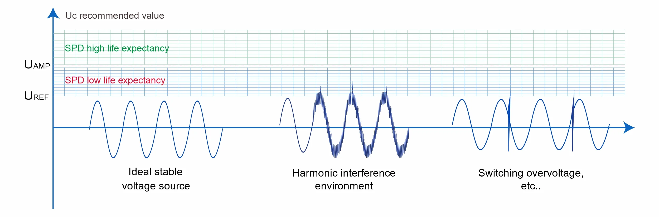
When considering the value of UC to choose the SPD, the basic requirements such as the operating voltage of a power source at the SPD installation location and the power distribution system should be considered, and then the system reference voltage (UREF) should be determined for model selection.
At the same time, wind power applications should especially consider whether there is harmonic interference at the installation location. If yes, the system operating voltage amplitude (UAMP) and the frequency of occurrence need to be considered, some areas with high switching frequency will have switching overvoltage, and some systems need to consider temporary overvoltage resulting from fault voltage (e.g. loss of neutral) and other situations.
As shown in the figure above, an SPD with a selected UC in the yellow area may operate frequently in the range of harmonic disturbances. This continuous operation will reduce the lifetime of the SPD. Therefore, it is recommended for wind power applications to select an SPD with an UC value in the green area, in order to have the service life prolonged.
Discharge current requirements – In & Iimp
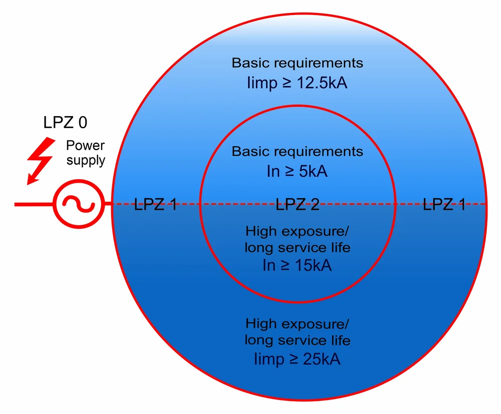
For a wind turbine, a matched discharge type SPD (Type 1+2+3) should be selected, according to the zone where the protection device is located, and meanwhile the exposure of the SPD installation position, the expected service life requirements, the power distribution system, the expected shunt size and other characteristics should be considered.
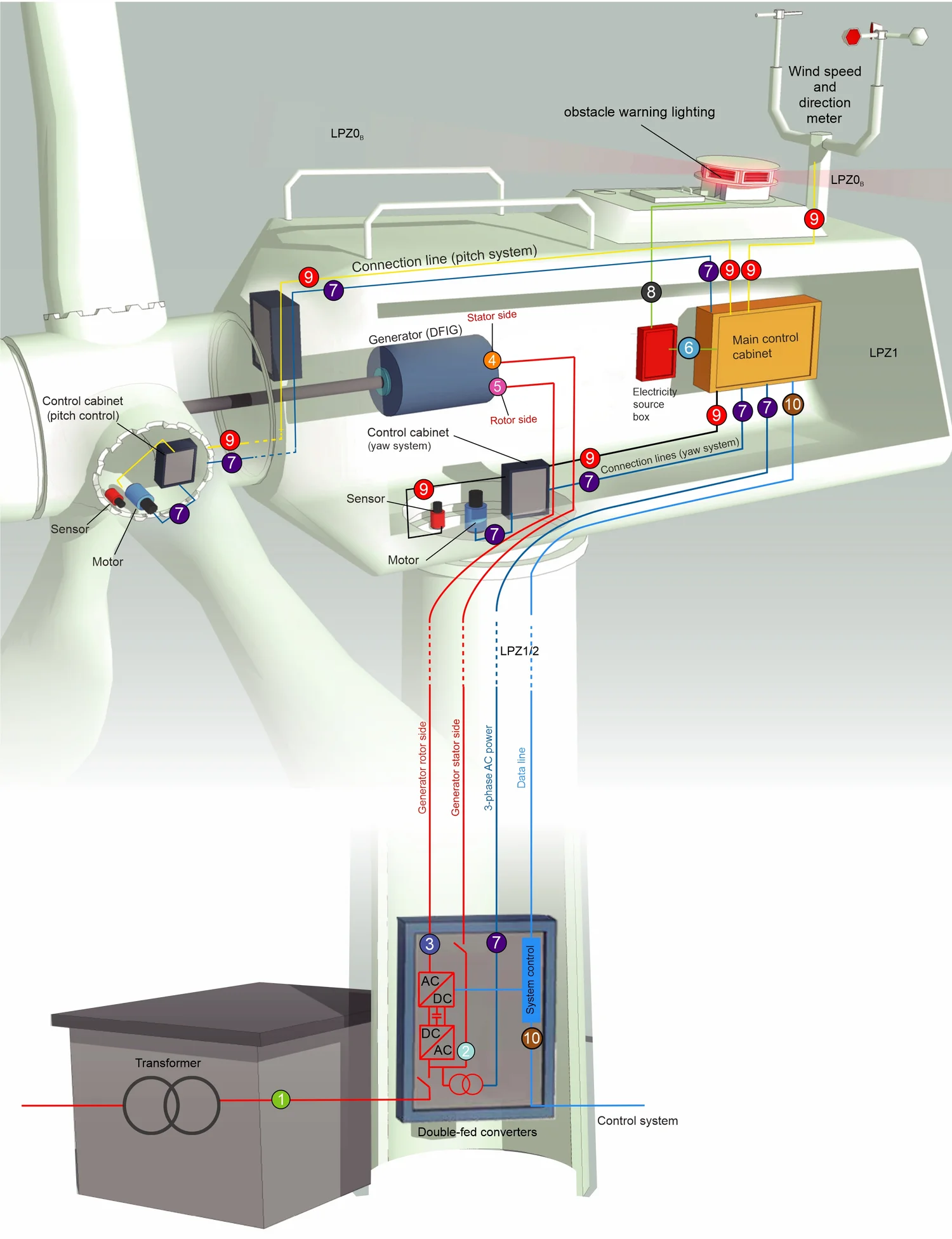
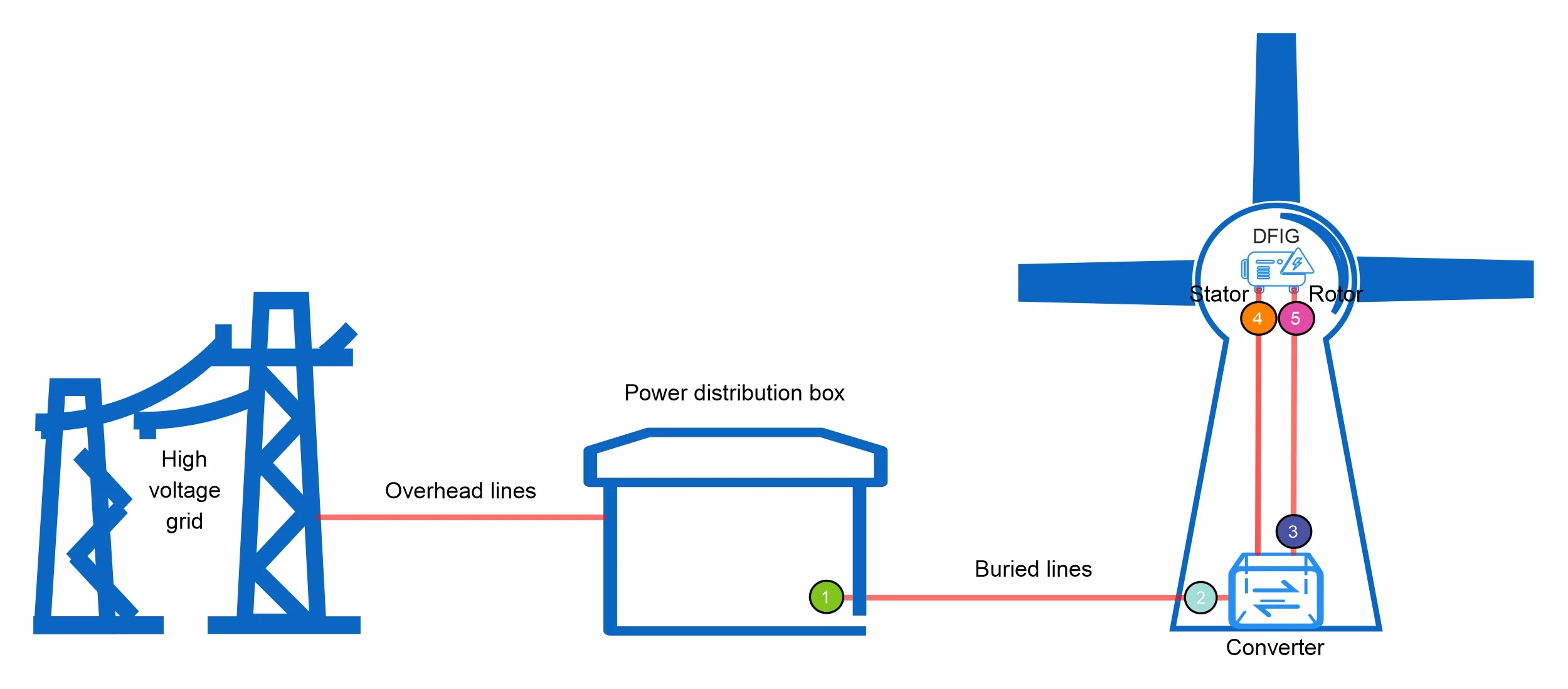
Examples of electrical systems for onshore wind DFIG models
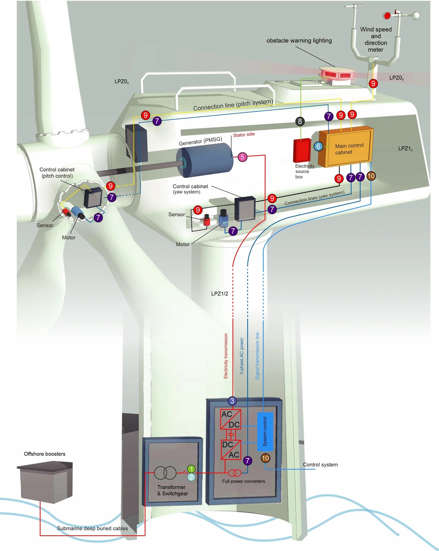
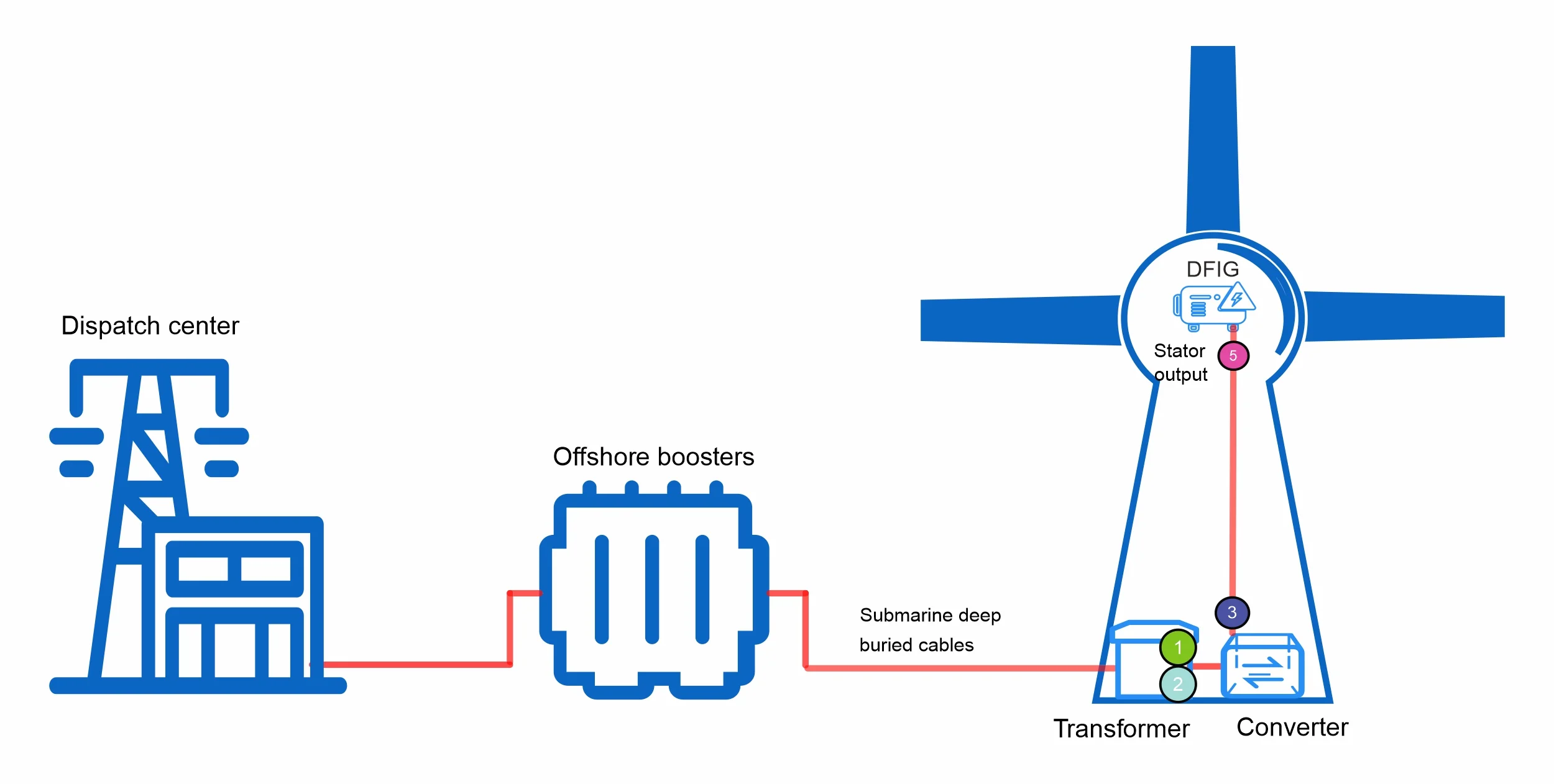
Example of electrical system for offshore wind PMSG models
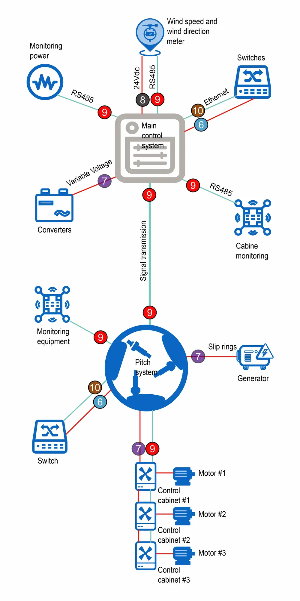
Example of wind turbine main control & pitch system

Due to their exposed location and height, wind turbines are vulnerable to the effects of direct lightning strikes. Several studies have shown that one must reckon with at least 10 direct lightning strikes to wind turbines in the multimegawatt range every year. The feed-in compensation must amortize the high investment costs within a few years, meaning that downtime caused by lightning and surge damage and the resulting repair costs must be avoided. For this reason, comprehensive lightning and surge protection measures are required.
When planning lightning protection measures, not only cloud-to-earth flashes but also earth-to-cloud flashes, so-called up-ward leaders, must be considered for objects in exposed locations with a height of more than 60 m. These occur primarily in the winter months with charges higher than Q = 300 C. It therefore makes sense to set higher requirements for conductor systems because it is the Q charges that are responsible for melting system parts and thus have a decisive influence on the maintenance of conductor systems, spark-gaps, etc. To give an example, the charge resulting from upward flashes during winter storms in Japan reached values of Q = 600 C.
The IEC 61400-24 (EN 61400-24) standard and GL 2010 guideline recommend protecting all sub-components of the lightning protection system of a wind turbine according to lightning protection level (LPL) I unless a risk analysis demonstrates that a lower LPL is sufficient. A risk analysis may also reveal that different sub-components have different LPLs. The IEC 61400-24 (EN 61400-24) standard recommends a comprehensive lightning protection concept.
Figure 1 – Rolling sphere method
Lightning protection (LP) for a wind turbine consists of an external lightning protection system (LPS) and surge protection measures (SPMs) for protecting electrical and electronic equipment.
In order to plan protection measures, it is advisable to subdivide the wind turbine into lightning protection zones (LPZs). The lightning protection system of a wind turbine protects two sub-systems that can only be found in wind turbines, namely the rotor blades and the mechanical drive train. The IEC 61400- 24 (EN 61400-24) standard describes in detail how to protect these special parts of a wind turbine and how to prove the effectiveness of the lightning protection measures.
The standard recommends verifying the lightning current withstand capability of these systems in high-current tests with the first stroke and the long stroke, if possible, in a common discharge.
The following describes how to implement lightning and surge protection measures for the electrical and electronic devices/systems of a wind turbine. The complex problems concerning the protection of the rotor blades and rotatable mounted parts/bearings must be examined in detail and depend on the manufacturer and type. The IEC 61400-24 (EN 61400-24) standard provides important information in this respect.
The lightning protection zone concept is a structuring measure To create a defined EMC environment in an object. This defined EMC environment depends on the immunity of the electrical equipment used. The lightning protection zone concept therefore, includes reducing conducted and field-bound interference at the boundaries to defined values as a protective measure. For this reason, the object to be protected is subdivided into protection zones.
The rolling sphere method is used to determine LPZ 0A, namely the parts of a wind turbine that may be subjected to direct lightning strikes, and LPZ 0B, namely the parts of a wind turbine that are protected from direct lightning strikes by external air-termination systems or air-termination systems integrated in parts of a wind turbine (for example in the rotor blade). According to the IEC 61400-24 (EN 61400-24) standard, the rolling sphere method may not be used for the rotor blade itself. For this reason, the design of the air-termination system should be tested according to subsection 8.2.3 of the IEC 61400-24 (EN 61400-24) standard.
Figure 1 shows a typical application of the rolling sphere method, Figure 4 the possible division of a wind turbine into different lightning protection zones. In this context, the division of a wind turbine into lightning protection zones depends on the design of the wind turbine. Therefore, the structure of the wind turbine should be observed. However, it is decisive that the lightning parameters that are injected into LPZ 0A from the outside are reduced by suitable shielding measures and surge protective devices at all zone boundaries so that there is no interference with the electrical and electronic devices and systems inside a wind turbine.
The nacelle should be designed as a closed metal shield. Thus, a volume with an electromagnetic field that is considerably lower than the field outside the wind turbine is generated in the nacelle. In accordance with IEC 61400-24 (EN 61400- 24), a tubular steel tower, which is frequently used for large wind turbines, can be regarded as an almost perfect Faraday cage for electromagnetic shielding. In the case of concrete hybrid towers, the function of the galvanic cage must be ensured by reinforcing steel as well as the earthing and electrical connection of the individual components. The switchgear and control cabinets in the nacelle and, if any, in the operations building should also be made of metal. The connecting cables should feature an external shield that is capable of carrying lightning currents.
Shielded cables are only resistant to EMC interference if the shields are connected to the equipotential bonding system at both ends. The shields must be contacted by means of fully (360 °) contacting terminals to prevent EMC-incompatible, long connecting cables in the wind turbine.
Magnetic shielding and cable routing should be performed as per section 4 of IEC 62305-4 (EC 62305-4). For this reason, the general guidelines for an EMC-compatible installation practice according to IEC / TR 61000-5-2 should be observed.
Shielding measures include, for example:
These include:
The function of an external lightning protection system (LPS) is to intercept direct lightning strikes including lightning strikes to the tower of a wind turbine and to discharge the lightning current from the point of strike to the ground. An external lightning protection system is also used to distribute the lightning current in the ground without causing thermal or mechanical damage or dangerous sparking which may lead to fire or explosion and endanger people.
The rolling sphere method can be used to determine potential points of strike for a wind turbine (except for the rotor blades) (Figure 1). For wind turbines, the recommendation is to use class of LPS I. Therefore, a rolling sphere with a radius r = 20 m is rolled over the wind turbine to determine the points of strike. Air-termination systems are required where the sphere touches the wind turbine (potential points of strike).
The nacelle construction should be integrated in the lightning protection system to ensure that lightning strikes to the nacelle hit either natural metal parts that are capable of withstanding this stress or an air-termination system designed for this purpose.
GRP-coated nacelles or the like should be fitted with an air-termination system and down conductors forming a cage around the nacelle (metal braid). The air-termination system including the bare conductors in this cage should be capable of withstanding lightning strikes according to the relevant lightning protection level. Other conductors in the Faraday cage should be designed in such a way that they can withstand the amount of lightning current to which they may be subjected.
The IEC 61400-24 (EN 61400-24) standard requires that air-termination systems for protecting measurement equipment, etc. mounted outside the nacelle be designed in compliance with the general requirements of lEC 62305-3 (EN 62305-3) and that down conductors be connected to the cage described above.
Natural components made of conductive materials which are permanently installed in/on a wind turbine and remain un-changed (e.g., lightning protection system of the rotor blades, bearings, mainframes, and hybrid tower) may be integrated in the LPS. When wind turbines consist of metal construction, it can be assumed that they fulfill the requirements for an external lightning protection system of class of LPS I according to IEC 62305 (EN 62305).
This requires that the lightning strike be safely intercepted by the lightning protection system of the rotor blades so that it can be discharged to the earth-termination system via the natural components such as bearings, mainframes, the tower and/or bypass systems (e.g., open spark gaps, carbon brushes).
As can be seen in Figure 1, the
may be hit by lightning. If they are capable of safely intercepting the maximum lightning impulse current of 200 kA and discharging it to the earth-termination system, they can be used as natural components of the air-termination system of the wind turbine’s external lightning protection system.
A metallic receptor, which represents a defined point of strike for flashes, is frequently attached to the tip of the GRP blade to protect the rotor blades from lightning strikes. A down conductor is routed from the receptor to the blade root. In case of a lightning strike, it can be assumed that lightning hits the blade tip (receptor) and then travels through the down conductor inside the blade via the nacelle and the tower to the earth-termination system.
The earth-termination system of a wind turbine must perform several functions such as personal protection, EMC protection and lightning protection. Materials, configurations and minimum cross-sectional areas can be taken from Table 6 of IEC 62305-3.
An effective earth-termination system (Figure 3) is essential to distribute lightning currents and to prevent the wind turbine from being destroyed. Moreover, the earth-termination system must protect people and animals against electric shock. In case of a lightning strike, the earth-termination system must discharge high lightning currents to the ground and distribute them in the ground without causing dangerous thermal and/ or electrodynamic effects.
In general, it is important to install an earth-termination system for a wind turbine which is used to protect the wind turbine against lightning strikes and to earth the power supply system.
Note: Electrical high-voltage regulations such as CENELEC HO 637 S1 or applicable national standards describe how to design an earth-termination system to prevent high touch and step voltages caused by short circuits in high or medium-voltage systems. With regard to the protection of human life, the IEC 61400-24 (EN 61400-24) standard refers to IEC / TS 60479-1 and IEC 60479-4.
The IEC 62305-3 (EN 62305-3) standard describes two basic types of earth electrode arrangements for wind turbines:
Type A: According to the informative Annex I of IEC 61400-24 (EN 61400-24), this arrangement cannot be used for wind turbines themselves, but for adjoining buildings (for example, buildings containing measurement equipment or office sheds for the wind farm). Type A earth electrode arrangements consist of horizontal or vertical earth electrodes connected to the building by at least two down conductors.
Type B: According to the informative Annex I of IEC 61400-24 (EN 61400-24), type B earth electrodes must be used for wind turbines. They either consist of a buried external ring earth electrode and/or a foundation earth electrode. Ring earth electrodes and metal parts in the foundation must be connected to the tower construction.
In any case, the reinforcement of the tower foundation should be integrated in the earth-termination system of a wind turbine.
Figure 2 – Example of an air-termination system for the weather station and the aircraft warning light
To ensure an earth-termination system ranging over as large an area as possible, the earth-termination system of the tower base and the operations building should be connected by means of a meshed earth electrode network. Corrosion-resistant ring earth electrodes (made of stainless steel (V4A), e.g. material No. AISI / ASTM 316 Ti) with potential control prevent excessive step volt- ages in case of a lightning strike and must be installed around the tower base to ensure personal protection (Figure 3).
Foundation earth electrodes make technical and economic sense and are required in the German Technical Connection Conditions (TAB) published by German distribution network operators. They are part of the electrical installation and fulfill essential safety functions. For this reason, they must be installed by or under the supervision of an electrician.
The metals used for earth electrodes must comply with the materials listed in Table 7 of lEC 62305-3 (EN 62305-3). The corrosion behavior of metal in the ground must be observed at all times.
Figure 3 – Earth-termination system of a wind turbine
Foundation earth electrodes should be made of galvanized or non-galvanized (round or strip) steel. Round steel must have a minimum diameter of 10 mm, while strip steel must have minimum dimensions of 30 mm x 3.5 mm. This material must be covered with at least 5 cm thick layer of concrete (corrosion protection). The foundation earth electrode must be connected to the main earthing busbar in the wind turbine. Corrosion-resistant connections must be established via fixed earthing terminals or terminal lugs made of stainless steel (V4A). Moreover, a ring earth electrode made of stainless steel (V4A) must be installed in the ground.
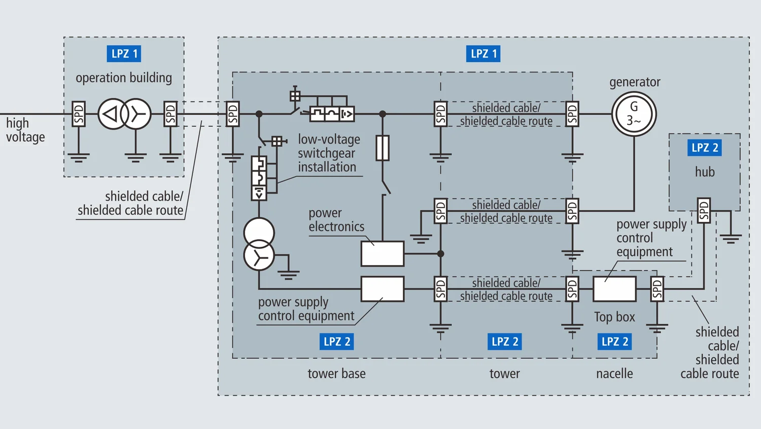
To ensure the safe operation of electrical and electronic devices, the boundaries of the lightning protection zones (LPZs) must be shielded against field-based interference and must be protected against conducted interference (Figures 4 and 5). To this end, surge protective devices that are capable of discharging high partial lightning currents without destruction must be installed at the transition from LPZ 0A to LPZ 1 (also referred to as lightning equipotential bonding).
These surge protective devices are referred to as type 1 lightning current arresters and are tested by means of impulse currents of 10/350 μs waveform. At the transition from LPZ 0B to LPZ 1 and higher, only low-energy impulse currents caused by voltages induced on the system or surges generated in the system must be coped with. These surge protective devices are referred to as type 2 surge arresters and are tested by means of impulse currents of 8/20 μs waveform.
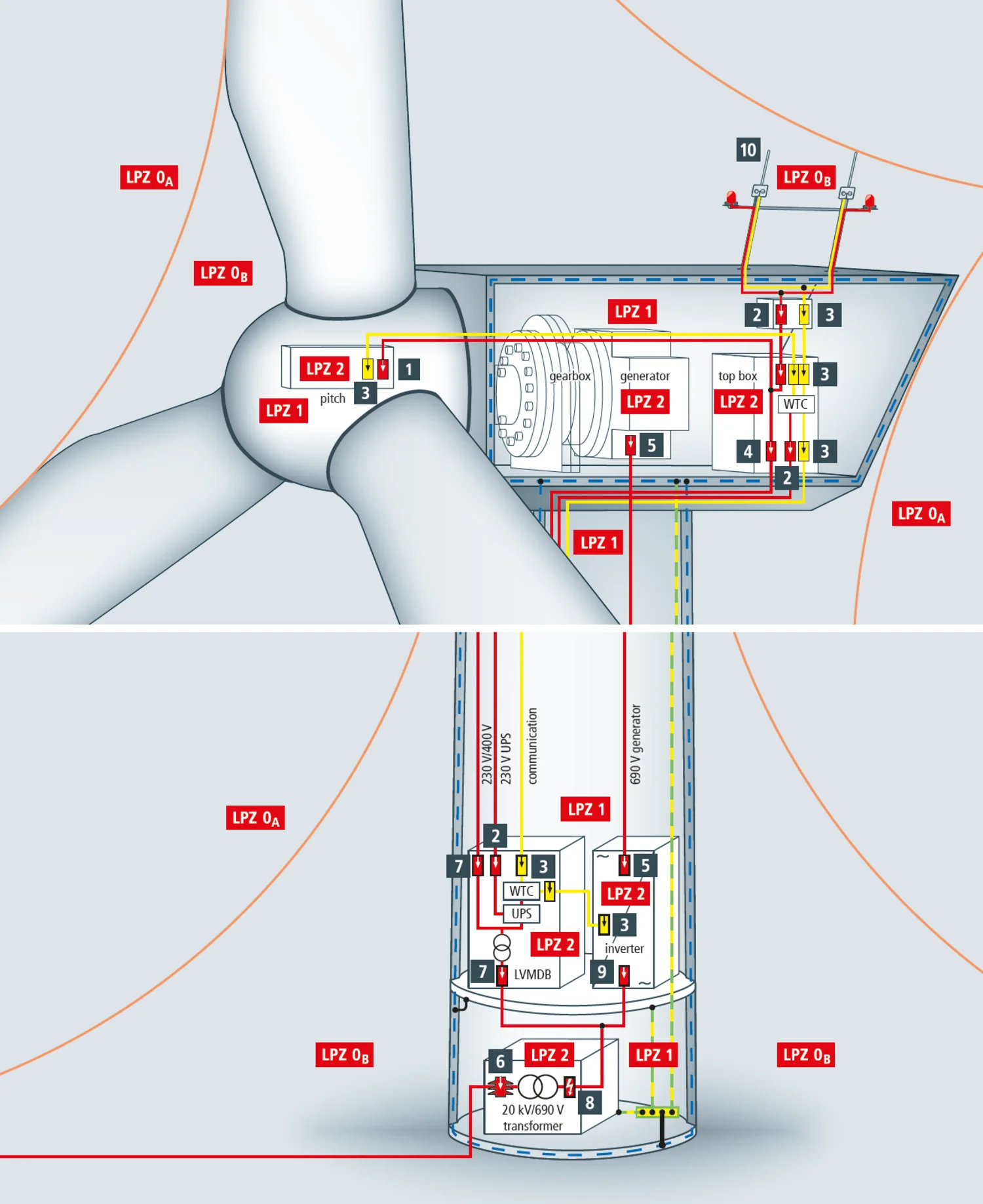
Figure 4 – Lightning and surge protection for a wind turbine
According to the lightning protection zone concept, all incoming cables and lines must be integrated in the lightning equipotential bonding system by means of type 1 lightning current arresters at the boundary from LPZ 0A to LPZ 1 or from LPZ 0A to LPZ 2. This affects both power supply and communication lines. An additional local equipotential bonding system where all cables and lines entering this boundary are integrated must be established for every further zone boundary within the volume to be protected. Type 2 surge arresters must be installed at the transition from LPZ 0B to LPZ 1 and from LPZ 1 to LPZ 2, whereas type 3 surge arresters must be provided at the transition from LPZ 2 to LPZ 3. The function of type 2 and type 3 surge arresters is to further reduce the residual interference of the upstream protection stages and to limit the surges induced on the wind turbine or generated in the wind turbine.
To describe the required voltage protection level UP in an LPZ, the immunity levels of the equipment located in an LPZ must be defined, e.g., for power lines and connection of equipment according to lEC 61000-4-5 (EN 61000-4-5) and lEC 60664-1 (EN 60664-1), for telecommunication lines and connection of equipment according to lEC 61000-4-5 (EN 61000-4-5), ITU-T K.20 and ITU-T K.21 and for other lines and connection of equipment according to the manufacturer’s instructions.
Manufacturers of electrical and electronic components or devices should be able to provide the required information on the immunity level according to the EMC standards. If this is not the case, the wind turbine manufacturer should perform tests to determine the immunity level. The specific immunity level of components in an LPZ directly defines the voltage protection level required at the LPZ boundaries. The immunity of a system must be proven, where applicable, with all SPDs installed and the equipment to be protected.
The transformer of a wind turbine may be housed at different locations (in a separate distribution station, in the tower base, in the tower, in the nacelle). In the case of large wind turbines, for example, the unshielded 20 kV cable in the tower base is routed to the medium-voltage switchgear installation consisting of a vacuum circuit breaker, mechanically locked selector switch disconnector, outgoing earthing switch, and protective relay. The medium-voltage cables are routed from the medium-voltage switchgear installation in the tower of the wind turbine to the transformer which may be situated in the tower base or in the nacelle (Figure 4). The transformer feeds the control cabinet in the tower base, the switchgear cabinet in the nacelle, and the pitch system in the hub by means of a TN-C system (L1, L2, L3, PEN conductor). The switchgear cabinet in the nacelle supplies the electrical equipment in the nacelle with an a.c. voltage of 230/400 V.
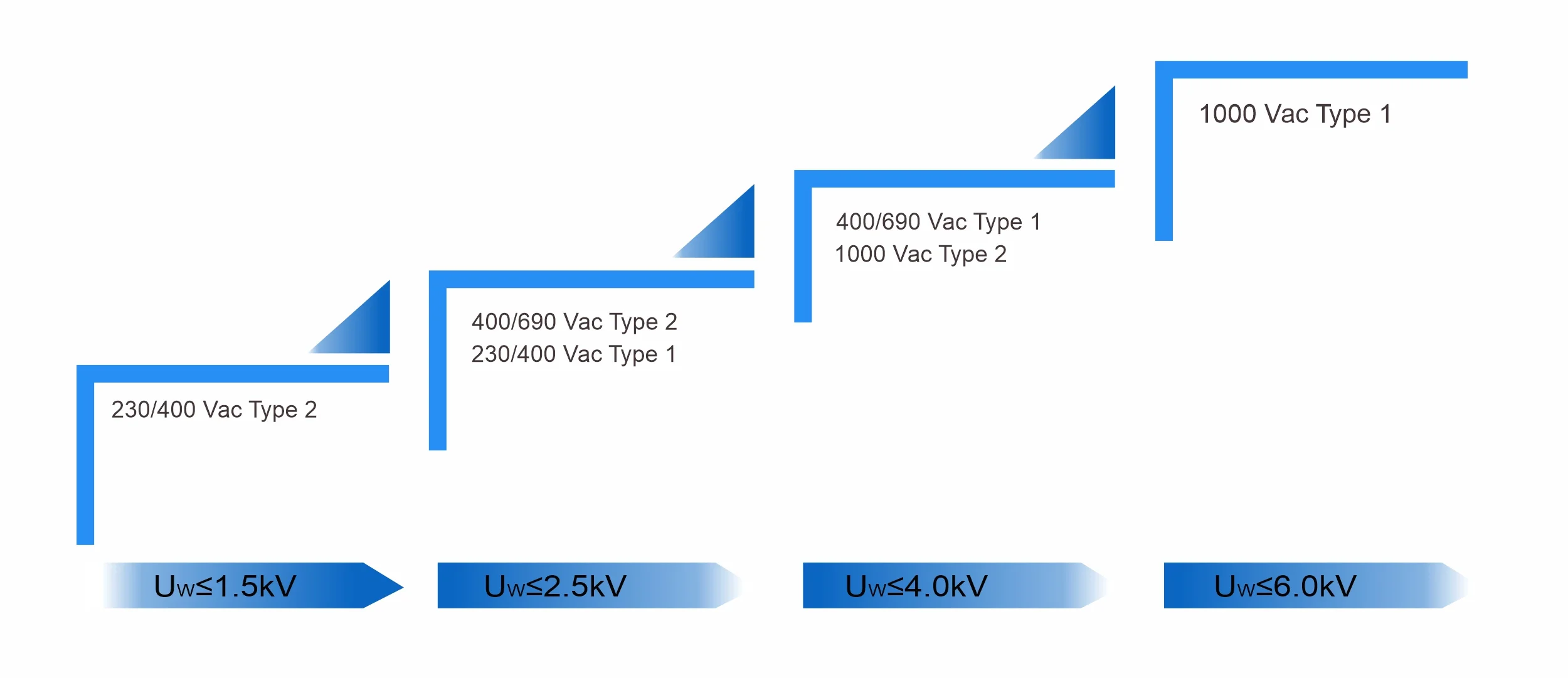
According to IEC 60364-4-44, all pieces of electrical equipment installed in a wind turbine must have a specific rated impulse withstand voltage according to the nominal voltage of the wind turbine (see IEC 60664-1 (EN 60664-1): Table 1, insulation coordination). This means that the surge arresters to be installed must have at least the specified voltage protection level according to the nominal voltage of the wind turbine. Surge arresters used to protect the 400/690 V supply must have a minimum voltage protection level Up ≤ 2.5 kV, whereas surge arresters used to protect the 230/400 V supply must have a voltage protection level Up ≤ 1.5 kV to ensure protection of sensitive electrical/electronic equipment. Surge protective devices shall be capable of discharging lightning currents of 10/350 μs waveform without destruction and shall have a voltage protection level of Up ≤ 2.5 kV.
The medium-voltage transformer infeed is protected by medium-voltage arresters which must be adapted to the system configuration and voltage of the medium-voltage system (Figure 9).
Figure 5 – Example of arresters installed at the zone boundaries of a wind turbine
Type 2 surge arresters, for example, SLP40-275/3S, should be used to protect the voltage supply of the control cabinet in the tower base, the switchgear cabinet in the nacelle and the pitch system in the hub by means of a 230/400 V TN-C system.
The aircraft warning light on the sensor mast in LPZ 0B should be protected by a type 2 surge arrester at the relevant zone transitions (LPZ 0B – 1, LPZ 1 – 2). Depending on the system, components of the SLP40 series (low voltage) and/or FRD series, for example, can be used for extra low voltage/signal lines.
Coordinated single-pole lightning current arresters with a high follow current limitation for the 400/690 V systems, for example FLP25-440 series, must be installed to protect the 400/690 V transformer, inverters, mains filters and the measurement equipment. It must be ensured at the frequency converter that the arresters are dimensioned for the maximum voltage peaks, which are higher than in the case of pure sinusoidal voltages. In this context, surge arresters with a nominal voltage of 600 V and Umov = 750 V have proven their worth. The SLP40-600/3S arresters can be installed at both sides of the converter (grid and machine side) and on the generator. Only if doubly-fed induction generators are used, must an arrester combination with an increased electric strength be used on the rotor side.
For this purpose, it is advisable to install the high-capacity arrester SLP40-1000/3S designed for continuous operating voltages of up to 1000 V and discharge currents up to 40 kA (8/20 μs). The internal series connection of a varistor and gas discharge tube ensures that the SPD does not activate in the event of temporary over-voltages up to 2200 Vpeak. Nevertheless, a very low protection level Up ≤ 5 kV is achieved. A suitable solution is also available for larger voltage peaks of up to 3 kV (with a protection level of ≤ 10 kV) in the form of a 3+1 Neptune circuit consisting of three arresters and a spark-gap-based arrester for potential separation.
Surge arresters for protecting electronic equipment in telecommunication and signaling networks against the indirect and direct effects of lightning strikes and other transients are described in IEC 61643-21 (EN 61643-21) and are installed at the zone boundaries in conformity with the lightning protection zone concept. Multi-stage arresters must be designed without blind spots, in other words it must be ensured that the different protection stages are coordinated with one another. Otherwise not all protection stages will be activated, thus causing faults in the surge protective device. Glass fiber cables are frequently used for routing information technology lines into a wind turbine and for connecting the control cabinets in the tower base to the nacelle. Shielded copper cables are used to connect the actuators and sensors to the control cabinets. Since interference by an electromagnetic environment is excluded, the glass fiber cables do not need to be protected by surge arresters unless they have a metal sheath which must be integrated in the equipotential bonding system either directly or by means of surge protective devices.
In general, the following shielded signal lines connect the actuators and sensors with the control cabinets must be protected by surge protective devices:
The signal lines (4 – 20 mA interfaces) between the sensors of the weather station and the switchgear cabinet are routed from LPZ 0B to LPZ 2 and can be protected by means of FRD2-24 or FRD4-24.
A universal DT-CAT 6A/EA surge arrester can be used if information between the nacelle and the pitch system is exchanged via 100 MB Ethernet data lines. This arrester is designed for Industrial Ethernet and similar applications in structured cabling systems according to class E up to 250 MHz for all data services up to 48 V DC and protects four pairs.
Alternatively, a DT-CAT 6A/EA arrester can be used to protect the 100 MB Ethernet data lines. This surge protective device is a prewired standard patch cable with an integrated surge arrester.
LSP’s reliable surge protection devices (SPDs) are designed to meet the protection needs of installations against lightning and surges. Contact our Experts!
Copyright © 2010-2024 Wenzhou Arrester Electric Co., Ltd. All Rights Reserved. Privacy Policy


