Why Surge Protection is Essential for Modern Electronics
Reliable electrical power is fundamental for today’s electronic systems, but temporary overvoltage events-commonly called power surges, voltage spikes, or transients-pose a serious threat. These high-energy events can originate from lightning strikes, utility grid switching, or cycling of large inductive loads. Sensitive microprocessor-based devices are particularly vulnerable; surges can cause immediate catastrophic damage or latent failures that shorten component lifespan.
To mitigate these risks, the Metal Oxide Varistor (MOV) has become a widely adopted and cost-effective solution in MOV surge protection. Its fast response to overvoltage conditions helps prevent damage to critical electronic circuits. This guide provides a detailed technical overview of MOV surge protection circuits, covering operational principles, circuit design strategies, component selection, and essential safety practices for reliable protection.
What is a Metal Oxide Varistor (MOV) and How It Protects Circuits
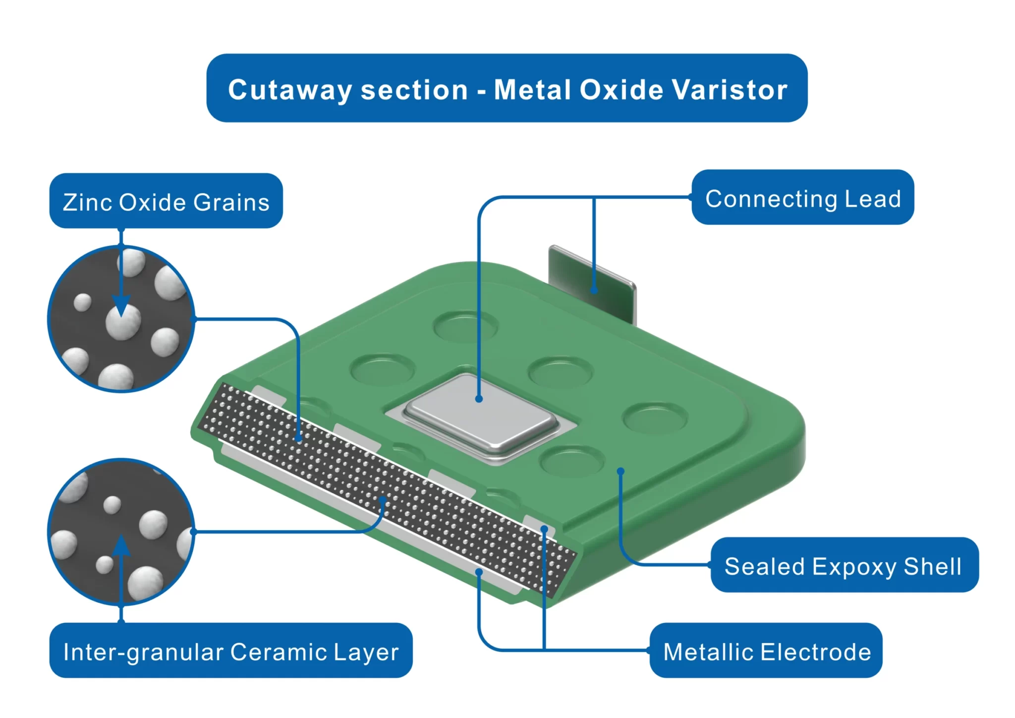
The Metal Oxide Varistor (MOV) is a cornerstone of MOV surge protection technology and the most widely used type of varistor today. An MOV is a nonlinear resistor whose resistance changes dramatically with applied voltage. It is primarily composed of a ceramic zinc oxide matrix, with sintered grains forming a complex semiconductor structure often doped with small amounts of other metal oxides like bismuth. Compared to older silicon carbide technologies, zinc oxide offers superior surge-handling performance.
During normal voltage conditions, the MOV exhibits very high resistance (mega-ohm range), allowing negligible leakage current and uninterrupted power to downstream equipment. When a transient overvoltage occurs, the MOV’s polycrystalline structure responds almost instantaneously: its resistance drops to a few ohms or less, forming a low-resistance path that conducts the surge away from sensitive electronics. This high-speed transition occurs in nanoseconds, ensuring rapid protection.
How an MOV Protects Equipment

The primary function of an MOV is to bypass surge energy rather than absorb it entirely. During a voltage spike, the MOV switches to a low-resistance state, diverting surge current safely to neutral or ground. While some energy is converted to heat within the MOV, this minor internal degradation is a trade-off to protect the more valuable downstream circuitry.
Understanding the MOV’s Voltage-Current (V-I) Curve
The V-I characteristic curve illustrates the MOV’s behavior under varying voltages:
- Leakage Region: At normal voltages, a minimal leakage current flows; resistance is high and the curve is nearly flat.
- Knee (Breakdown) Region: Near the rated breakdown voltage, resistance drops sharply, allowing significant current conduction.
- Clamping Region: During surges, the MOV maintains a nearly constant clamping voltage even as surge current increases exponentially. This clamping effect limits voltage exposure to protected devices, ensuring their safety.
The Fundamental MOV Surge Protection Circuit Diagram
A robust MOV surge protection circuit requires the Metal Oxide Varistor (MOV) to be installed in parallel with the load it safeguards. In single-phase AC systems-common in homes, offices, and power supplies-an effective circuit addresses both differential and common-mode surges. The standard multi-mode protection topology typically includes the following MOV placements:
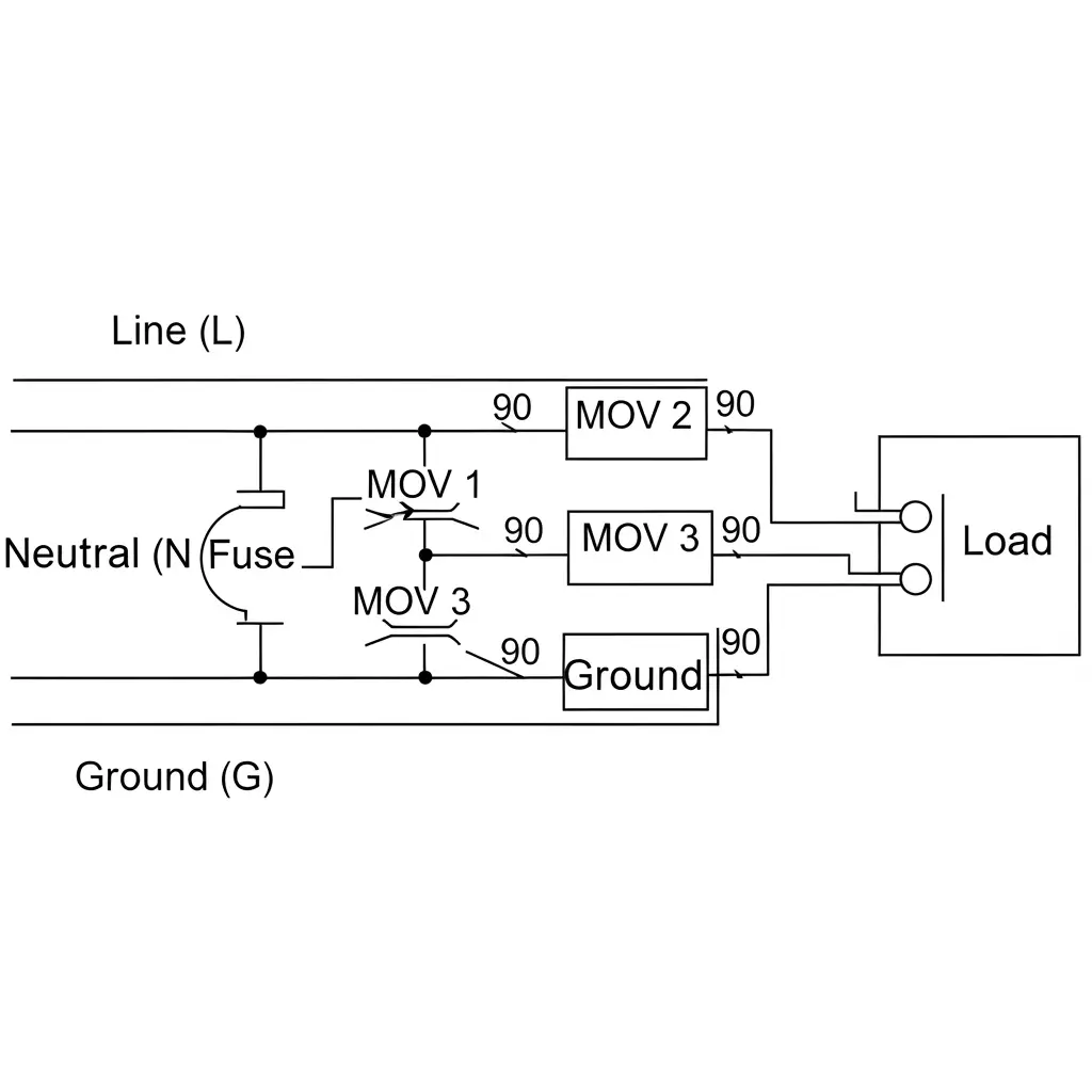
- Line-to-Neutral (L-N) Protection – MOV 1: Protects against differential mode surges between Line and Neutral, which are the most frequent surge events in typical AC circuits.
- Line-to-Ground (L-G) Protection – MOV 2: Guards against common-mode surges where both Line and Neutral rise sharply relative to Ground. Such surges often occur during lightning events or large utility grid faults, including neutral loss scenarios.
- Neutral-to-Ground (N-G) Protection – MOV 3: Ensures protection from common-mode surges affecting Neutral and Ground, maintaining proper ground reference and safeguarding sensitive electronics, particularly in industrial or high-reliability systems.
Proper placement of MOVs in these key positions ensures multi-level defense, clamping voltage spikes effectively and prolonging the lifespan of connected equipment.
How to Select the Right MOV: Step-by-Step Technical Guide

Choosing the appropriate Metal Oxide Varistor (MOV) is critical to ensure effective surge protection while maintaining safety. Selecting an incorrect MOV can lead to early failure, ineffective protection, or safety hazards. Follow these professional guidelines:
Step 1: Determine the Maximum Continuous Operating Voltage (MCOV)
The MCOV is the maximum RMS voltage an MOV can tolerate continuously without conduction. It must exceed the nominal system voltage to accommodate normal grid fluctuations.
- Rule of Thumb: Choose an MOV with an MCOV approximately 15–25% above the nominal line voltage.
- 120 V AC System: Typical MCOV selection is 130–150 V AC.
- 230 V AC System: Typical MCOV is 275 V AC (commonly listed as UC on datasheets).
Technical Note: MOV thickness correlates directly with voltage rating-the thicker the MOV, the higher its voltage tolerance.
Step 2: Match Surge Current Ratings (Imax, In) and Energy (Joules)
These parameters define the MOV’s durability and energy-handling capability. Physical size usually determines these ratings:
- Larger diameter MOVs can absorb higher surge currents.
- Example: 20 mm MOV → In ≈ 5 kA, Imax ≈ 10 kA
- 25 mm MOV → In ≈ 10 kA, Imax ≈ 20 kA
- 34 mm MOV → In ≈ 20 kA, Imax ≈ 40 kA
Key Parameters:
- Imax (Peak Surge Current): Maximum current for a single standardized 8/20 μs pulse. Higher exposure locations (service entrance) require 40 kA+, while device-level protection may use 5–10 kA.
- In (Nominal Discharge Current): Maximum repeated surge current (e.g., 15 pulses) the MOV can handle without significant degradation. Typically, In ≈ 0.5 × Imax.
- Energy Absorption (Joules): Indicates the total surge energy the MOV can safely dissipate over its lifetime.
Step 3: Verify Clamping Voltage for Your Application
The clamping voltage is the residual voltage that appears across the MOV (and thus your protected load) when it is actively shunting a specified surge current. This is the final and most crucial protection check.
- The Rule: The clamping voltage of the MOV must be less than the maximum voltage the downstream equipment can safely withstand. If the clamping voltage is too high, the surge will still damage your device despite the MOV’s presence.
Guide to Selecting the Right MOV for an SPD: Practical Examples
Choosing the correct Metal Oxide Varistor (MOV) for a Surge Protective Device (SPD) requires careful reference to technical datasheets. The following examples illustrate how to match SPD specifications with an appropriate MOV part number.
Example 1: MOV for a Type 2 AC SPD

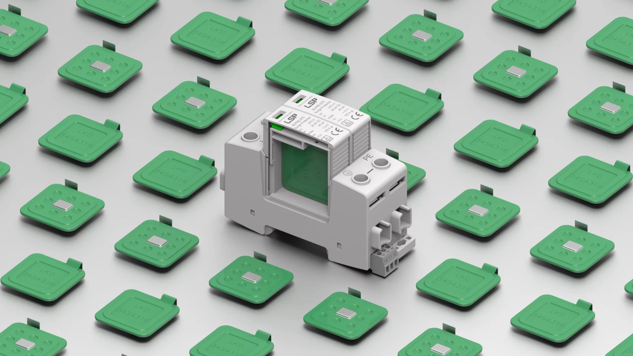
- SPD Model: SLP40-275 series (Un = 230 V AC, UC = 275 V AC, In = 20 kA, Imax = 40 kA)
- Selection Process: Refer to the MOV technical datasheet (e.g., LKD 34SxxxK Specification). Locate the column labeled Maximum Allowable Voltage (ACrms) or Maximum Continuous Operating Voltage (UC) and find the value 275 V. The corresponding MOV model is 34S431K.
Example 2: MOV for a Type 1+2 AC SPD


- SPD Model: FLP12,5-275 series (Un = 230 V AC, UC = 275 V AC, In = 20 kA, Imax = 50 kA, Iimp = 12.5 kA)
- Selection Process: Download the MOV technical datasheet (e.g., LKD 54SxxxK-1 Specification). Search the Maximum Allowable Voltage (ACrms) column for 275 V. The matching MOV is 54S431K-1.
Example 3: MOV for a Type 2 DC SPD (U-Configuration)


- SPD Model: SLP-PV600 (UCPV = 600 V DC, In = 20 kA, Imax = 40 kA)
- Selection Process: Refer to the MOV datasheet (e.g., LKD 34SxxxK Specification). Find the Maximum Allowable Voltage (DC) slightly above 600 V, e.g., 670 V. The corresponding MOV model is 34S821K.
Example 4: MOV for a Type 2 DC SPD (Y-Configuration)


- SPD Model: SLP-PV1000 (UCPV = 1000 V DC, In = 20 kA, Imax = 40 kA)
- Selection Process: In a Y-configuration, voltage is shared across multiple MOVs. Refer to the datasheet and locate 585 V in the Maximum Allowable Voltage (DC) column. Two MOVs stacked together achieve the required total voltage. The selected model is 34S711K.
The Hidden Danger: MOV Lifespan, Degradation, and Safety Fusing
A Metal Oxide Varistor (MOV) has a finite lifespan. Each surge it shunts causes a small, irreversible change in its internal ceramic structure. Over time:
- Clamping voltage may drift downward.
- Leakage current under normal operation can increase.
- Eventually, the MOV reaches end-of-life.
The most common failure mode is short-circuit, not open-circuit. As the MOV degrades, increased leakage current generates heat. This can trigger thermal runaway, where heat causes more current, leading to overheating, smoke, and potentially fire-a catastrophic failure scenario.
Safety Measures: Mandatory Fusing To prevent such failures, professional SPD designs always include overcurrent or thermal protection devices in series with the MOV. Common solutions include:
| Protection Device | Description | Function |
| Fuse | A properly rated fuse opens the circuit if the MOV shorts | Prevents catastrophic failure |
| Thermal Fuse / Thermal Cutoff (TCO) | Temperature-sensitive fuse bonded to the MOV body; opens the circuit if the MOV overheats | Prevents thermal runaway and ensures superior safety |
Key Takeaways:
- Never rely solely on the MOV for protection-always include series fusing.
- Regular inspection and testing of the fuse and TCO can prevent device failure.
- Correct sizing of the fuse ensures the SPD can handle rated surge currents without risk.
From Component to Certified Solution: The Value of a Professional SPD
Proper MOV selection, multi-mode configuration, and safe fusing are critical for effective surge protection. Mistakes in MCOV, energy rating, or omitting thermal protection can render a protection scheme ineffective or even hazardous, especially in complex AC/DC power systems. For mission-critical applications, a pre-engineered, certified SPD solution is far more reliable than a DIY assembly.
As a manufacturer specializing in surge protective devices (SPD) since 2010, we integrate component selection, design, and safety validation into every product. Our approach ensures:
- MOV moisture resistance and lightning endurance
- GDT surge absorption precision
- Flame-retardant and corrosion-resistant materials
This integration guarantees that the final SPD is more than just a collection of components-it is a fully validated solution. Pre-verified modules simplify selection for customers, matching the MOV, GDT, and system specifications to ensure optimal surge protection. We use LKD brand MOVs (trusted by global top-10 SPD manufacturers) and Vactech GDTs (used by industry leaders like Phoenix Contact). Innovative chamber designs allow MOVs and GDTs to work together, consistently passing 8/20 μs (Type 2) and 10/350 μs (Type 1) tests, with a service life exceeding 5 years, supported by a 5-year warranty.
All SPDs undergo rigorous testing, including surge impact, thermal stability, salt spray, and glow-wire tests, and are fully compliant with IEC/EN 61643-11 standards. Certifications include ISO9001, TUV, CB, and CE, providing system-level assurance of long-term reliability and safety.
Advanced Strategy: Hybrid SPD Circuits with MOV, TVS, and GDT
For high-performance protection, MOVs are often combined with TVS diodes and GDTs in hybrid circuits. Each technology has distinct characteristics:
| Feature | MOV | TVS Diode | GDT |
| Response Time | Fast (nanoseconds) | Extremely fast (picoseconds) | Slow (microseconds) |
| Energy Capacity | High | Low voltage, low energy | Very high |
| Clamping Precision | Moderate | High | Low |
| Lifespan | Degrades with each surge | Minimal degradation | Very long, robust |
| Typical Use | AC power line protection | Low-voltage DC/data lines | Primary high-energy diversion |
A hybrid SPD often uses a GDT at the entrance for high-energy surges, an MOV for secondary shunting, and a TVS diode for precise, low-voltage clamping at sensitive loads. This configuration provides complete protection from high-energy surges to sensitive electronics.
Conclusion: Moving from Parts to Certified Protection
Surge protection is essential for operational stability and asset safety. While MOVs are fundamental components, proper selection, circuit topology, and thermal/fuse protection are key to reliable performance. The most robust approach is to implement certified, integrated SPD solutions rather than relying on individual parts.
At LSP, our certified SPDs offer end-to-end protection, combining tested components, validated design, and international standard compliance. To safeguard critical systems against inevitable surges, consult with our team for a professional SPD strategy that delivers not only devices but complete, reliable protection. The MOV circuit is the heart of an SPD. To see how it fits into a complete system, check our surge protection device wiring diagram. And different surge protection device types employ MOVs in various configurations. Learn which type suits your application.
FAQ: Common Questions About MOV-Based Surge Protection
What is an MOV and how does it protect my electrical devices?
A: A Metal Oxide Varistor (MOV) is a voltage-dependent, non-linear resistor that clamps excessive voltage during a surge event. When a transient overvoltage occurs, the MOV quickly switches from high to low resistance, diverting surge energy safely to the ground or neutral line, thereby protecting connected electronics.
Can an MOV prevent damage from lightning or power surges?
A: An MOV is effective against indirect lightning surges and everyday voltage spikes caused by grid switching or large equipment operation. It cannot withstand a direct lightning strike, which requires external lightning protection like rods, down conductors, and grounding grids.
How do I select the right MOV for my surge protection circuit?
A: Choose an MOV based on the maximum continuous operating voltage (MCOV), clamping voltage, nominal discharge current (In), and maximum surge current (Imax). Ensure the selected MOV is suitable for the system voltage and expected surge environment. Multi-mode SPD configurations, combining Line-to-Neutral, Line-to-Ground, and Neutral-to-Ground MOVs, enhance overall protection.
How long does an MOV last and what causes it to fail?
A: Every surge event slightly degrades the MOV’s internal ceramic structure. Over time, leakage current increases and clamping voltage can shift. Without proper series fusing (thermal fuse or overcurrent protection), an MOV may fail catastrophically via thermal runaway. Properly fused MOVs typically last for 5+ years under normal surge conditions.
Is a surge protector with MOV enough for comprehensive protection?
A: A standalone MOV or SPD is not enough. Full surge protection requires proper grounding, correct installation near power entry points, and, for high-risk areas, multi-level SPDs combined with external lightning protection systems. Signal line protection may also be needed for telecom, network, or antenna connections.
What maintenance is needed for MOV-based SPDs?
A: Periodically inspect SPDs for indicator status, measure grounding resistance, and track cumulative surge exposure if the SPD includes a lightning counter. Replace MOV modules showing signs of degradation or if the SPD has experienced surges beyond its rated capacity.
Can I use the same MOV for AC and DC surge protection applications?
A: MOVs are available for both AC and DC systems, but their voltage ratings differ. DC applications often require a slightly higher maximum allowable voltage to prevent premature conduction. Verify datasheets carefully and consider Y- or U-configurations for multi-MOV setups in PV or industrial DC systems.
Can a surge protector protect against lightning?
A: Yes, but only for indirect lightning effects. The MOV acts like a “safety valve,” clamping overvoltage and preventing sensitive equipment damage. Direct lightning carries energy far beyond the SPD’s design and requires external lightning rods, down conductors, and grounding grids.