If you have ever stared at a power protection product page wondering whether you need a surge protector or a voltage stabilizer, you have plenty of company. The two devices look similar on the surface, and plenty of product descriptions blur the line between them. But they solve fundamentally different problems, and picking the wrong one means your equipment stays unprotected against the threat that actually matters in your situation.
This guide breaks down exactly what each device does, where their capabilities overlap (they do not), the weaknesses nobody talks about, and a practical framework to decide what you actually need — whether you are protecting a home office, a factory floor, or anything in between.
The Two Electrical Threats You Need to Understand
Before we talk about devices, we need to talk about problems. Electrical power does not fail in just one way. There are two distinct categories of power trouble, and they require two different kinds of defense.
Transient overvoltage — also called a surge or spike — is a sudden, violent jump in voltage that lasts for microseconds. A lightning strike near a power line can induce 1,000 to 6,000 volts onto the wire. Grid switching operations and large motors cycling on and off create smaller but still dangerous spikes. The defining characteristic: the event is over almost before it begins — typically in less than 100 microseconds, per the surge environment defined in IEC 61643-11.
Sustained voltage deviation is the opposite problem. Instead of a split-second spike, you get voltage that runs too high or too low for minutes, hours, or all day. Common causes: aging distribution networks, overloaded transformers during peak hours, heavy equipment on the same feeder line, or simply living in a region where the grid is unreliable by default. A 220V system might drift to 187V during a brownout or climb to 253V late at night when demand drops — both are within the ±15% range that IEEE 1159 classifies as a long-duration voltage variation.
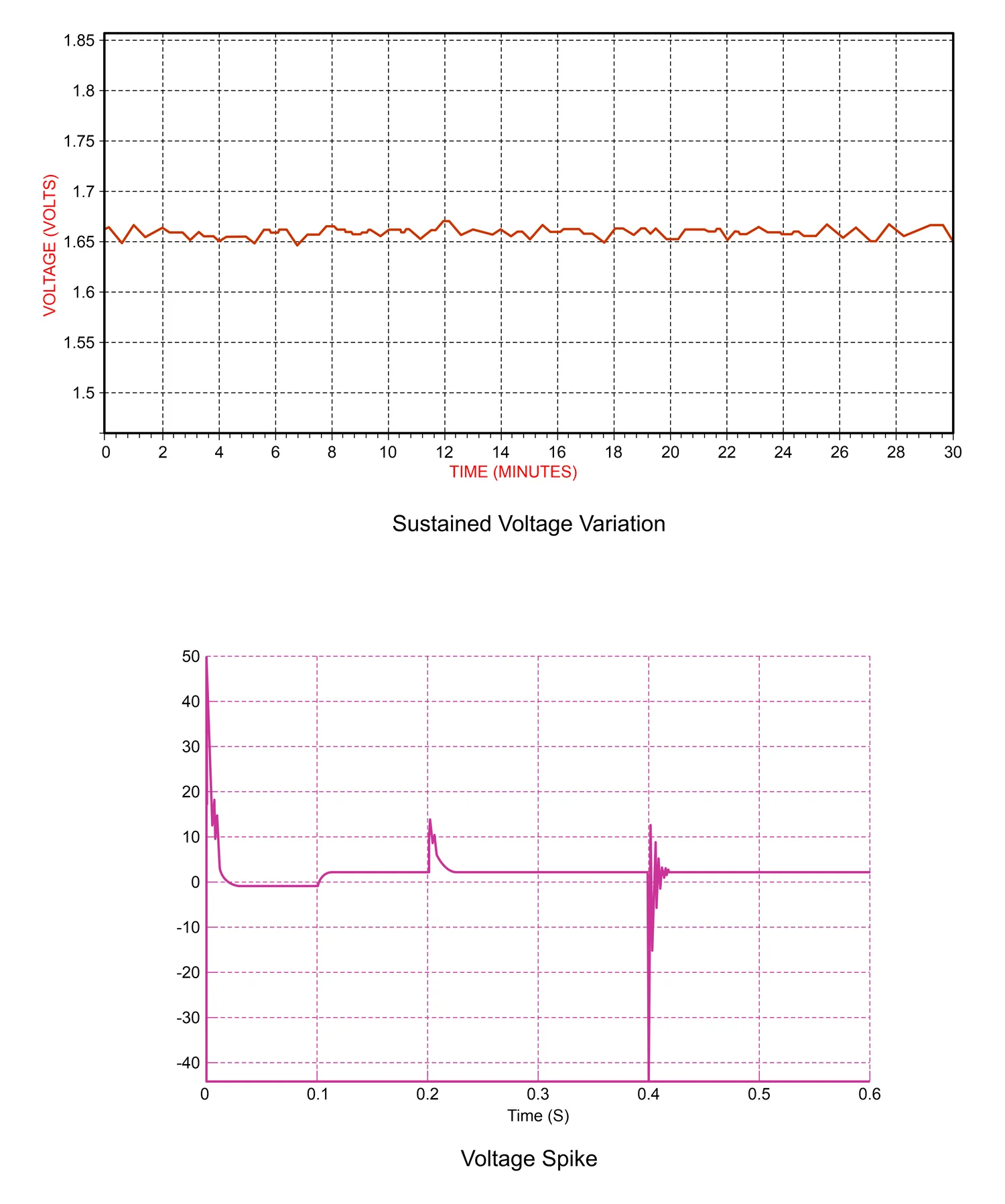
Think of it this way: a transient surge is like a sudden wave crashing over a seawall — violent, short, and gone. Sustained voltage deviation is like the tide slowly rising over several hours. You do not use the same tool to handle both, and if you only prepare for one, the other will catch you off guard.
What Is a Surge Protector?
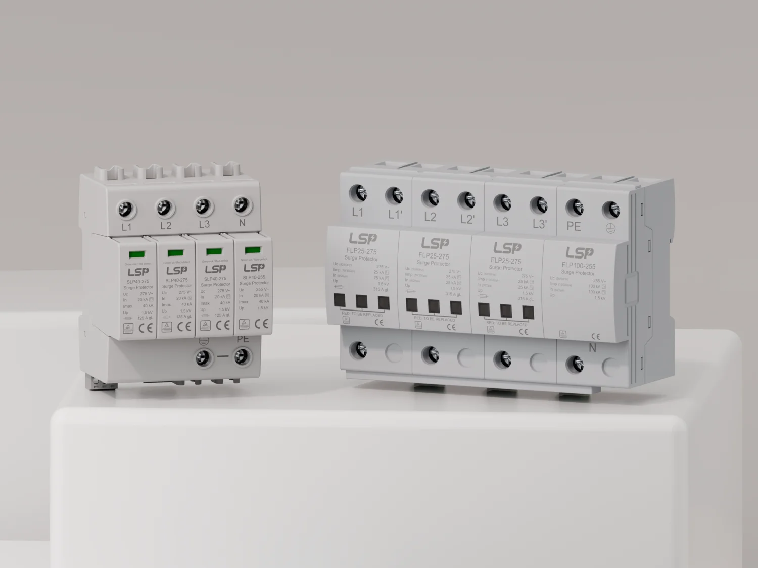
A surge protective device (SPD) — commonly called a surge protector — is designed to do one thing: detect a voltage spike and divert the excess energy to ground before it reaches your equipment.
The core component inside most SPDs is the metal oxide varistor (MOV). Under normal voltage, an MOV behaves like an open valve — it has extremely high resistance and lets no current through. But when the voltage across it exceeds a threshold called the clamping voltage, the MOV’s resistance collapses almost instantly. Within 25 nanoseconds, it switches from an insulator to a conductor, shunting thousands of amps of surge current toward the ground wire. Once the surge passes, it returns to its high-resistance state, ready for the next event.
What does this protect against? Lightning-induced surges on power lines, voltage spikes when the utility switches grids, and the back-EMF kick from large motors and compressors shutting off. These are all transient events — high magnitude, extremely short duration.
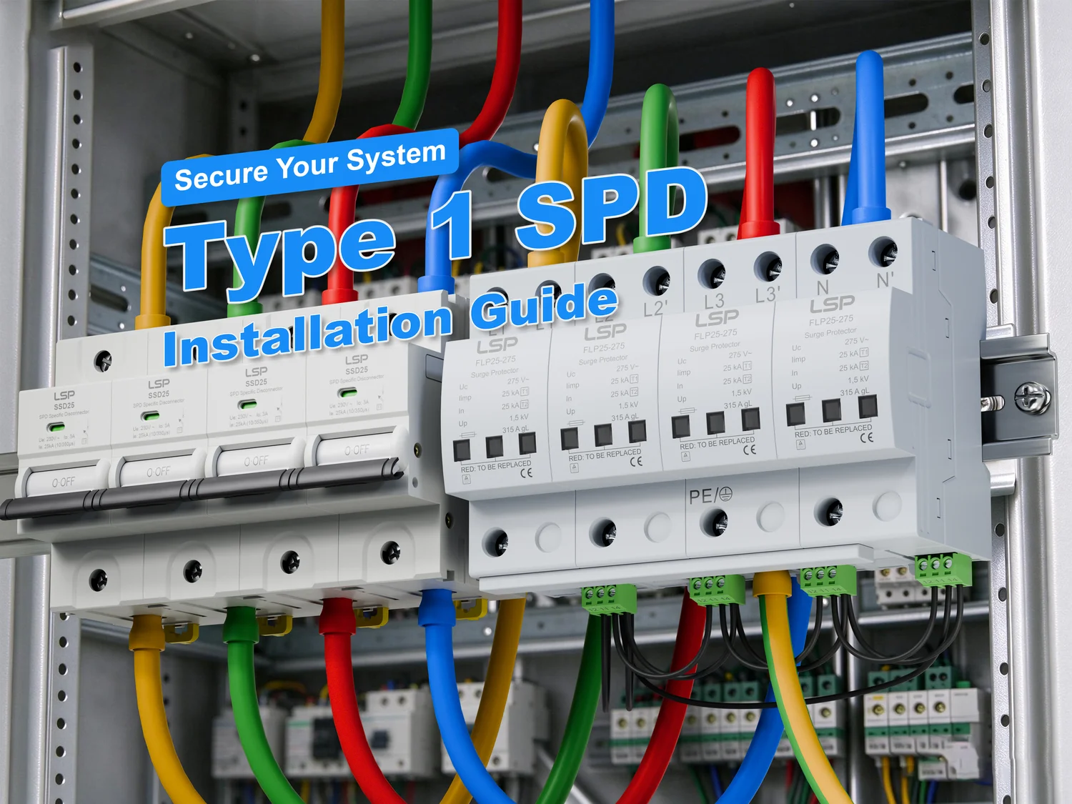
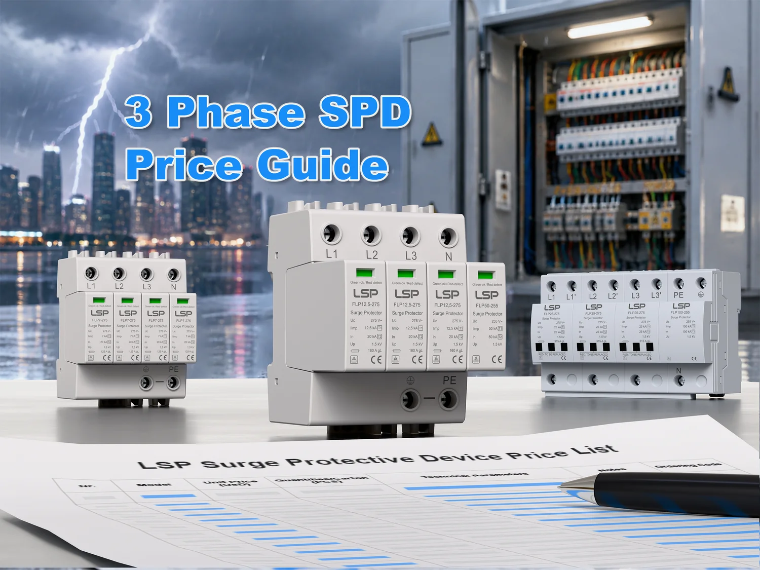
SPDs come in several forms, from the familiar power-strip style to hardwired units installed inside electrical panels. The IEC 61643-11 standard classifies them into three types based on where they sit in the electrical system and how much energy they are rated to handle: Type 1 at the main service entrance, Type 2 at distribution panels, and Type 3 at the point of use. We will come back to why that classification matters when we talk about building a complete protection plan.
A useful way to think about a surge protector: it is like a pressure-relief valve on a boiler. When pressure spikes beyond safe limits, the valve opens and vents steam. It does not regulate the boiler’s normal operating pressure — it only reacts to emergencies. The SPD works the same way: it ignores normal voltage and only activates when a dangerous spike arrives.
What Is a Voltage Stabilizer?
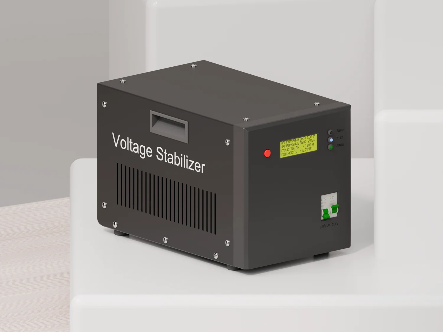
A voltage stabilizer — also called a voltage regulator or automatic voltage regulator (AVR) — addresses the other category of power trouble. Its job is continuous: it monitors the incoming voltage and actively adjusts the output to stay within a safe, steady range.
Internally, a stabilizer works through one of several mechanisms. The most common type uses a multi-tap transformer paired with relays or a servo motor. When the input voltage drops below the target, the stabilizer switches to a higher transformer tap to boost it. When the voltage climbs too high, it switches to a lower tap to step it down. More advanced solid-state (static) stabilizers use power electronics to achieve the same result with no moving parts and tighter regulation accuracy — typically ±1% compared to ±8–10% for relay-type units.
This is a fundamentally different operation from a surge protector. A stabilizer does not divert energy to ground. It does not react to microsecond-scale events. Its response time is measured in milliseconds — 10 to 20 milliseconds for a relay-type unit, faster for servo and static models. That is fast enough to keep a motor or compressor running smoothly through a brownout, but far too slow to catch a lightning-induced spike that rises and falls in under 100 microseconds.
A stabilizer protects against: chronic low voltage that causes motors to overheat and stall, sustained overvoltage that degrades insulation and shortens equipment life, and the kind of flickering-lights voltage instability common in areas with aging grid infrastructure or heavy industrial loads nearby.
The right mental model: a voltage stabilizer is like the cruise control in a car. Going uphill, it adds throttle; going downhill, it backs off. It maintains a constant speed regardless of terrain — or in this case, a constant output voltage regardless of what the grid is delivering. But cruise control does not brake for an obstacle in the road — and a stabilizer does not stop a lightning surge.
Surge Protector vs Voltage Stabilizer — Key Differences at a Glance
Now that we understand each device individually, here is how they compare across the dimensions that matter for your decision.
| Dimension | Surge Protector (SPD) | Voltage Stabilizer |
|---|---|---|
| Core function | Diverts voltage spikes to ground | Actively regulates output to a stable level |
| Threat type | Transient overvoltage (microsecond spikes) | Sustained voltage deviation (brownouts, overvoltage, fluctuations) |
| Typical threat magnitude | 1,000–6,000V (lightning-induced), duration <100 μs per IEC 61643-11 | ±15% of nominal voltage (e.g., 187–253V on a 220V system), duration minutes to hours per IEEE 1159 |
| Working mechanism | MOV switches from high-resistance to conductor within 25 ns, shunts current to ground | Transformer tap-changing via relays, servo motor, or solid-state electronics |
| Response time | <25 nanoseconds | 10–500 milliseconds |
| Protection duration | Instantaneous — only during the spike event | Continuous — active as long as the device is powered |
| Typical applications | Computers, servers, TVs, networking equipment, electronics with microprocessors | Refrigerators, air conditioners, washing machines, pumps, equipment with motors and compressors |
| Relative cost | $10–200 (plug-in); $100–500+ (panel-mounted) | $50–500 (appliance-level); $500–3,000+ (whole-facility) |
Where Each Device Belongs — Application Scenarios
Theory is helpful, but the real question is practical: which device goes where? Here is how the decision maps to specific types of equipment.
| Equipment Type | Primary Threat | Recommended Device | Why |
|---|---|---|---|
| Desktop computers, laptops, servers | Lightning-induced surges, switching transients | Surge protector | Microprocessors operate within ±5–10% voltage tolerance; a split-second spike destroys sensitive ICs instantly |
| Home theater systems, TVs, gaming consoles | Grid switching surges, nearby lightning | Surge protector | HDMI boards and power supply circuits are surge-sensitive and expensive to replace |
| Network routers, modems, switches | Induced surges on data lines | Surge protector (signal-line SPD recommended) | Ethernet and coax lines act as surge antennas |
| Refrigerators, freezers | Chronic low voltage, brownouts | Voltage stabilizer | Compressors stall and overheat when voltage drops below 90% of rating (NEMA MG1) |
| Air conditioners, heat pumps | Voltage sag during compressor startup | Voltage stabilizer | AC compressors draw 5–7× running current at startup; low voltage can cause locked-rotor burnout |
| Washing machines, water pumps | Voltage fluctuation, brownouts | Voltage stabilizer | Induction motors run hotter and lose torque under sustained low voltage |
| Industrial PLCs, VFDs, control panels | Both — surges + chronic instability | Both (Type 2 SPD + stabilizer) | PLCs combine microprocessors with noisy industrial feeders; downtime costs far exceed protection costs |
| Medical devices, lab instruments | Both — cannot tolerate either | Both (Type 2/3 SPD + static stabilizer) | Patient safety and measurement accuracy demand the tightest protection |
| LED lighting systems | Switching surges, nearby lightning | Surge protector | LED drivers contain sensitive rectifier circuits |
| Data center racks, server rooms | Both + UPS | Both (Type 1+2 SPD + UPS with AVR) | Layered architecture is standard practice |
The pattern is clear: equipment built around microchips fears voltage spikes. Equipment built around motors and compressors fears voltage instability. Equipment that has both — like a modern inverter air conditioner or an industrial automation panel — needs both types of protection.
The Limitations No One Talks About
Every power protection article tells you what these devices can do. Almost none tell you what they cannot — and more importantly, when they quietly stop working. Understanding these limitations is not optional. A false sense of security is more dangerous than no protection at all.
What a Surge Protector Won’t Tell You
Three uncomfortable truths about SPDs that every buyer should know.
First, MOVs are consumable parts. Every surge an MOV absorbs leaves microscopic damage in its zinc oxide grain structure. The grain boundaries that give the varistor its nonlinear voltage-current characteristic degrade incrementally with each event. Over time — or after a single large surge — the leakage current through the MOV rises, its clamping voltage drifts, and eventually it can no longer protect anything. What makes this dangerous is that the degradation is invisible. The “protected” LED on your power strip can stay lit long after the MOVs inside have lost most of their surge-handling capacity. Industry guidance considers a ±10% change in varistor voltage from its initial value as the end-of-life threshold (In Compliance Magazine, 2019).
Second, SPDs cannot handle sustained overvoltage. If your grid voltage runs at 270V for an hour instead of spiking to 6,000V for a microsecond, the MOV enters continuous conduction, heats up rapidly, and can enter thermal runaway — a self-reinforcing cycle where rising temperature causes rising leakage current, which causes more heating, until the device shorts out, smokes, or catches fire. This is why any serious SPD design includes a thermal disconnection mechanism — a solder joint or spring-loaded contact that physically separates the MOV from the circuit before it reaches ignition temperature.
Third, an SPD is useless without a low-impedance path to ground. The entire operating principle relies on diverting surge current into the earth. If your building’s ground resistance is high — a common situation in older structures, rural areas, and many developing countries — most of that surge energy never reaches the ground. Instead, it finds alternative paths, potentially through your equipment. IEC 60364-5-54 specifies a maximum ground resistance of 10 ohms for effective protection. We will explore this in more detail in the grounding section below.
These failure modes are not inevitable. They are engineering problems with engineering solutions. High-quality SPDs address MOV degradation at the component selection stage — specifying varistors with tight ±10% tolerance from reputable wafer suppliers rather than the ±20% common in the market, and epoxy-sealing each MOV chip against moisture ingress that accelerates aging. Independent arc-extinguishing chambers physically isolate a failing MOV from the circuit before thermal runaway can propagate. And manufacturers who test every unit — not just batch samples — on both lightning impulse and thermal stability provide a fundamentally different reliability profile. LSP, for instance, builds its SPD line around these three design principles: precision-selected LKD MOVs, a proprietary flat-tripping mechanism with a dedicated arc chamber, and 100% unit-level dual-testing (LSP Global). None of this eliminates MOV aging — physics does not allow that — but it dramatically narrows the gap between rated specifications and real-world performance.
Why Voltage Stabilizers Aren’t Perfect Either
Voltage stabilizers have their own set of limitations that manufacturers rarely highlight.
The most fundamental is response speed. A relay-type stabilizer — the most common and affordable variety — takes 10 to 20 milliseconds to detect a voltage change and switch taps. During that switching window, the output voltage is completely unregulated. A lightning surge that lasts 50 microseconds has come and gone 200 to 400 times before the stabilizer even begins to react. If you rely on a stabilizer alone in a lightning-prone area, your equipment has zero protection against the fastest, most destructive events.
Second, mechanical wear is built into the design. Relay and servo-motor stabilizers contain moving parts — relay contacts that arc and pit with every tap change, carbon brushes that wear down on a rotating transformer winding. In an area with frequent voltage fluctuations, a relay stabilizer might switch taps dozens of times per hour, accumulating mechanical cycles far faster than the component ratings anticipate. A servo-motor carbon brush typically lasts 3 to 5 years under normal conditions. In a highly unstable grid, that can drop to 18 months.
Third, stabilizers consume power themselves. Transformer-based designs have inherent losses — core losses in the iron laminations, copper losses in the windings. A typical stabilizer operates at 90 to 95% efficiency, meaning a 5,000 VA unit dissipates 250 to 500 watts as heat even when the connected load is idle. Over a year of continuous operation, that adds up to a meaningful electricity cost that most buyers do not factor into their purchase decision.
None of this means stabilizers are a bad investment. For equipment with motors and compressors in unstable-grid regions, a stabilizer is often the single most cost-effective protection you can buy. But it should be chosen with clear eyes about what it can and cannot do — and never treated as a substitute for surge protection.
Grounding — The Protection Prerequisite Most People Overlook
Someone buys a high-quality surge protector, plugs in their expensive equipment, and feels safe. A lightning strike hits a nearby power line. The equipment is destroyed. The surge protector’s indicator light still shows green. This scenario repeats itself constantly, and the answer is almost always the same: the building had no effective ground.
Why Grounding Makes or Breaks Your Protection
A surge protector works by diverting excess current to ground. The keyword is to ground. The surge current’s path is: phase conductor → SPD → ground conductor → earth. If any segment of that path has high resistance, the current does not simply disappear — Ohm’s Law dictates that it generates voltage across that resistance instead.
Consider the math. A moderate surge event might push 1,000 amps through the SPD. If your ground resistance is 10 ohms — the maximum allowed by IEC 60364-5-54 — the voltage developed across the ground path is 1,000 A × 10 Ω = 10,000 volts. That voltage appears on what is supposed to be the “safe” side of your protector, and from there it reaches every piece of equipment connected to the same ground system.
If your ground resistance is 100 ohms — common in dry, sandy, or rocky soil, or in buildings where the ground rod has corroded over decades — that same 1,000 A surge produces 100,000 volts. At that point, the “protection” is purely cosmetic.
The NEC (NFPA 70, Article 250.53) takes a practical approach: a single ground rod must measure 25 ohms or less. If it does not, a second rod must be added at least 1.8 meters (6 feet) away. This is not an optional recommendation — it is the minimum legal standard for new construction in jurisdictions that follow the NEC. Yet a significant percentage of buildings worldwide — particularly older construction and structures in developing countries — do not meet even this baseline.
How to Check If Your Grounding Is Adequate
You do not need to be an electrician to get a rough sense of your grounding situation. Here is a three-level approach, from quick visual check to professional measurement.
Level 1 — Visual inspection (5 minutes, zero cost): Look at your wall outlets. Do they have three holes (hot, neutral, ground) or two? If they have two, you have no ground at the outlet — and a plug-in surge protector cannot function. Open your electrical panel. Is there a ground bus bar with green or bare copper wires attached? Is there a thick ground wire leaving the panel and heading toward the earth (typically through an exterior wall)? Look for obvious signs of trouble: corroded connections, wires that have pulled loose, ground rods that are visibly rusted through at the soil line.
Level 2 — Outlet testing (30 seconds per outlet, $10–20): A plug-in outlet tester with GFCI test capability immediately tells you whether each outlet is wired correctly and whether the ground is present and functional. For a voltage check, set a digital multimeter to AC volts and measure between neutral and ground. A reading under 2 volts generally indicates a healthy ground path. Between 2 and 5 volts is borderline. Above 5 volts, you almost certainly have a grounding problem that needs attention.
Level 3 — Professional ground resistance test: This requires a dedicated earth resistance tester using the three-point fall-of-potential method and should be performed by a licensed electrician. The target: 10 ohms or less for reliable surge protection, 25 ohms or less as a minimum. If your electrician reports a number above 25, plan for remediation.
What to Do When Proper Grounding Isn’t Available
Not everyone can install a textbook grounding system. Tenants cannot modify building electrical infrastructure. Older buildings may require prohibitively expensive rewiring. And in some regions, ground rods simply do not achieve low resistance due to soil conditions.
In these situations, a pragmatic layered approach provides meaningful — though not perfect — protection:
- Install an independent ground rod if you have access to soil (detached homes, ground-floor units with yard access). A copper-clad steel rod at least 16 mm in diameter and 2.4 meters long, driven to where the top sits 0.5 meters below grade, connected with a minimum 6 mm² copper conductor. This is a weekend DIY project if you are comfortable with basic electrical work; otherwise, budget roughly $200–400 for an electrician.
- Use equipotential bonding. Even if you cannot achieve a low-resistance path to remote earth, you can ensure that all metal surfaces within the building rise to the same voltage during a surge event — eliminating the voltage differences that cause current to flow destructively through equipment. Bond your electrical panel ground to water pipes (if metallic), structural steel, and any other large metal masses per IEC 60364-5-54 Section 542.
- Deploy a Type 1 SPD at the service entrance. Type 1 SPDs are designed to handle partial lightning currents (10/350 μs waveform) and can operate in systems with less-than-ideal grounding. They provide the first line of defense even when downstream protection is compromised. Combine this with a voltage stabilizer on critical circuits — the stabilizer handles the chronic voltage issues while the Type 1 SPD catches the catastrophic spikes.
A protection system is never “install and forget.” SPDs should be visually inspected quarterly — check that status indicators are green on every unit. After any major thunderstorm, check again. Voltage stabilizers should have their input and output voltages measured at least twice per year to confirm they are still regulating within specification.
How to Decide — A Practical Selection Framework
You now understand what each device does, what it cannot do, what hidden prerequisites determine whether it works at all, and what equipment needs which kind of protection. Here is how to synthesize all of that into a decision you can act on today.

When to Choose a Surge Protector (and How to Pick a Good One)
You are in this category if your power is generally stable — voltage stays within ±5% of nominal most of the time, you rarely see lights dim or flicker, and your main concern is the occasional thunderstorm or the surge when the building’s large AC unit cycles on.
If that describes your situation, a surge protector is likely the right starting point. When selecting one, focus on five specifications:
- Maximum continuous operating voltage (Uc): Must be at least 1.1× your nominal line voltage. On a 220–240V system, select Uc ≥ 275V. On a 120V system, Uc ≥ 150V.
- Nominal discharge current (In): For residential electronics, In ≥ 5 kA (8/20 μs waveform) is adequate. For a home panel-mounted unit or small commercial application, In ≥ 20 kA. For an industrial service entrance, In ≥ 20 kA with Imax ≥ 40 kA.
- Voltage protection level (Up): The lower the better. For sensitive electronics, look for Up ≤ 1.5 kV. Standard units range from 1.0 to 2.5 kV.
- Status indication and thermal disconnection: Non-negotiable. The unit must have a visible indicator (LED or mechanical flag) that shows whether protection is active, and an internal thermal disconnect that removes a failed MOV from the circuit. Without both, you have no way to know when protection has been lost.
- Certification: Look for products certified to IEC/EN 61643-11. In North America, UL 1449 listing. A TUV or CB certificate adds an independent verification layer. Uncertified SPDs may use undersized MOVs or omit the thermal disconnect entirely.
When a Voltage Stabilizer Is the Right Call
You are in this category if you experience any of these symptoms regularly: lights that flicker or visibly dim when appliances start, refrigerators or AC units that struggle to start or trip breakers frequently, electronic devices that reboot randomly, or a multimeter reading that consistently shows voltage 10% or more below nominal.
Calculate your stabilizer capacity by adding up the rated power (in watts or VA) of everything you plan to connect, then multiply by 1.5 to 2.0. The multiplier accounts for motor starting currents, which can briefly draw five to seven times the running current. A refrigerator rated at 300W may pull 1,500–2,100W for the first second of compressor startup — and if the stabilizer cannot deliver that, the compressor never starts, the motor stalls, and you are back to square one.
When choosing between stabilizer types, the trade-off is precision versus cost versus lifespan:
- Relay-type: ±8–10% regulation, lowest cost, 3–5 year typical lifespan. Best for general-purpose residential use where voltage is unstable but not wildly so.
- Servo-motor: ±1–3% regulation, mid-range cost, 3–5 year lifespan (carbon brush dependent). Best for sensitive equipment where tighter regulation justifies the premium.
- Solid-state (static): ±1% regulation, highest cost, 10+ year lifespan. Best for medical, laboratory, and industrial applications where precision and reliability outweigh upfront cost.
When You Need Both — and How to Set Them Up
If your power is both unstable (frequent voltage swings) and surge-exposed (thunderstorm region, industrial feeders, overhead lines), protecting your equipment requires both devices working together in a specific architecture.
The recommended three-tier setup:
Tier 1 — Service entrance: A Type 1 SPD at the main electrical panel. This unit handles direct and nearby lightning strikes, tested with the 10/350 μs impulse waveform with Iimp ≥ 12.5 kA. It provides coarse protection for the entire building.
Tier 2 — Distribution: At the sub-panel or immediately upstream of critical loads, install a voltage stabilizer sized for the connected circuits. Downstream of the stabilizer, add a Type 2 SPD (In ≥ 20 kA, 8/20 μs waveform) to clamp any residual surge voltage that made it past Tier 1.
Tier 3 — Point of use: At the outlet level, a Type 3 SPD power strip (In ≥ 5 kA, combination wave tested per IEC 61643-11) provides the final layer of fine protection for individual sensitive devices.
The installation order matters: wall outlet → voltage stabilizer → Type 3 SPD → equipment. The stabilizer must come before the SPD relative to the load, because the stabilizer’s control circuit itself can be damaged by a nanosecond spike. The Type 3 SPD at the end catches anything that remains after the upstream layers have done their work.
One essential practice regardless of your setup: inspect quarterly. Check every SPD’s status indicator. Measure your stabilizer’s output voltage against a known-good multimeter. After a major thunderstorm, check the SPDs the same day. Protection that you do not verify is protection you are only guessing you still have.
And a procurement note for anyone sourcing these devices in volume: selecting a manufacturer that covers the full Type range — Type 1 through Type 3 across both AC and DC applications — simplifies compatibility and warranty management across the entire protection architecture. Verified certifications (IEC/EN 61643-11, TUV, CB) and documented unit-level testing are the non-negotiable baseline; anything less means you are accepting unknown risk at every tier of your protection system.
A surge protector and a voltage stabilizer are not competitors. They are complementary tools that address different threats on different timescales. If your grid is stable, start with a quality SPD. If your voltage wanders, a stabilizer pays for itself in extended equipment life. If both problems exist — and in much of the world, they do — a properly installed layered system is not over-engineering. It is what “protected” actually means.