Every machine that stops unexpectedly shares one root cause with most others. The press halts mid-cycle, the packaging line drops offline at 2 a.m., and somewhere behind both failures is a decision made months earlier at a desk, in a schematic, in a bill of materials. PLC panel design is where machine reliability is actually decided, long before the first wire is cut.
This guide walks the full path of PLC control panel design: from the requirements you collect before touching CAD, through layout, component selection, wiring and grounding, to the tests that clear a panel for power-up. Two topics most guides skip get their own sections: surge protection inside the cabinet, and the in-house-versus-outsource decision every OEM faces.

First, Define What the Panel Must Do
A PLC panel is the physical home of the control system: the PLC itself, digital and analog I/O, a 24VDC power supply, circuit breakers, relays, terminals, an HMI, and the network switch that ties it together. The design does not start with a layout; it starts with a list of questions the layout must answer.
Skipping this step is the most expensive mistake in panel design. Every gap in the requirement list becomes a change order after the enclosure is drilled.
| Requirement dimension | What to ask | What happens if you skip it |
|---|---|---|
| I/O count and types | How many digital/analog points, which signal levels (24VDC, 120VAC, 4–20mA, 0–10VDC)? | PLC rack sized wrong; terminals added mid-build |
| Incoming power | Single-phase 230V or three-phase 480V? Control voltage 24VDC from where? | Transformer and breaker selection fails inspection |
| Environment | Temperature, dust, washdown, corrosion risk? | Wrong enclosure rating (NEMA 1 vs 4X / IP54 vs IP65) |
| Loads | Motors, heaters? Full-load current (FLA) for each? | Undersized contactors and overcurrent protection |
| Communications | EtherNet/IP, Modbus, Profinet? Which devices talk to the PLC? | Switches and cabling retrofitted after wiring |
| Future expansion | What gets added in five years? | A panel with no spare space is a rebuild waiting to happen |
The deliverable of this phase is a drawing package: schematic, BOM, physical layout, and an I/O table. That package, not the enclosure, is the design. Everything after this section is about making it honest.
Panel Layout: Zoning, Spacing, and the Space Nobody Plans For
There are only three grouping logics inside a panel: by voltage, by heat, by function. Any component placement that cannot justify itself under one of these rules is a future troubleshooting problem. Use the same test on every layout decision below.
Zone the Backplane: AC, DC, and Heat
Separate AC and DC sections of the backplane, and their grounding paths, onto opposite sides. The reason is not aesthetics. It cuts electromagnetic interference between power and signal circuits, and it changes who can safely open the door: a technician working inside a live 480V cabinet needs arc-flash PPE, while a 24VDC-only section can be serviced without suiting up. Panel builders on forums like PLCTalk consistently call for splitting voltage zones into separate cabinets for exactly this reason: plant maintenance people then reach the PLC without arc-flash gear.
Heat placement follows the same logic. Components that produce the most heat and tolerate it best (power supplies, VFDs, braking resistors) go high or near the ventilation path, so their heat rises away from electronics rated for lower temperatures. This is why the old argument about VFDs “top or bottom” has a practical answer: a VFD’s environment rating is often 40°C while surrounding electronics tolerate 70–80°C, so the VFD protects itself and derates; the components above it do not. Where cabinet temperature can exceed 40°C, active cooling stops being optional. And between any device and the wire duct, keep a minimum of 25mm. That gap is what lets the next person identify the cables.
Leave 25–50%: Spare Space and Service Access
Experienced designers budget spare space as a negotiation with the future, not an afterthought: 20–25% free area for machine-specific panels, and up to 40–50% on plant panels expected to serve for 30 years. The pushback from project managers is predictable; the counter is arithmetic. Replacement parts are rarely smaller than the ones they replace, wire ducts routinely carry double their original wire count, and every expansion needs new terminals.
The practical rule from the field: if you are not sure the enclosure is big enough, it is not. And the rule for access: components that need frequent service (breakers, interface relays, HMI connections) sit where a technician can reach them without removing anything else.
Component Selection: Your BOM Is the Design Contract
Every line on the bill of materials is a promise: who made this part, what certification backs it, and who answers when it fails. Before selecting anything, apply three questions to every candidate component: Does the certification exist, and does the production batch actually match the certified sample? If this part dies on a Friday night, can a replacement be on site within days? A BOM that cannot answer these questions is a draft, not a design.

Power Path: Disconnect, Breakers, and the 25–30% Supply Margin
Convention places the main disconnect and incoming breaker at the upper right of the enclosure, feeding distribution from there. Size the 24VDC power supply by summing every load and adding a 25–30% margin. A system drawing 3A gets at least a 4A supply (Eabel, 2025). The margin buys certainty: an overloaded supply does not fail cleanly, it sags, and a sagging supply makes PLCs reboot randomly and outputs chatter.
Protect each output branch individually, and remember that the short-circuit current rating (SCCR) of the whole panel is a system property. The breaker combination must survive the available fault current at the incoming terminals, which is exactly the calculation UL 508A inspections check (AutomationDirect via Processing Magazine, 2022). One more non-negotiable: the emergency stop is hardwired to remove power from the output circuits. It never depends on PLC logic.
PLC, I/O, and Relays: What Goes Between Field and Logic
Choose the PLC by three things: I/O count, processing load, and the communication protocols the plant actually uses. Then design the interface layer for maintenance, not just function. Prefer digital output cards wired to slim interface relays over relay output cards: when one relay wears out, and relays always wear out, the repair is a single replacement cube, not an entire output card plus a program download.
For digital inputs, three-tier terminal blocks land the sensor wire, +24V, and 0V in one place. Installers quietly appreciate this for years after the build: there is a fused supply terminal where the sensor needs it, instead of one shared +24V terminal expected to receive sixteen field wires. Match your PNP/NPN (sourcing/sinking) convention between PLC inputs and sensors, and note the shield rule here as well: shielded signal cables ground at the PLC end only, never both.
Surge Protection: The Component Most Panels Forget
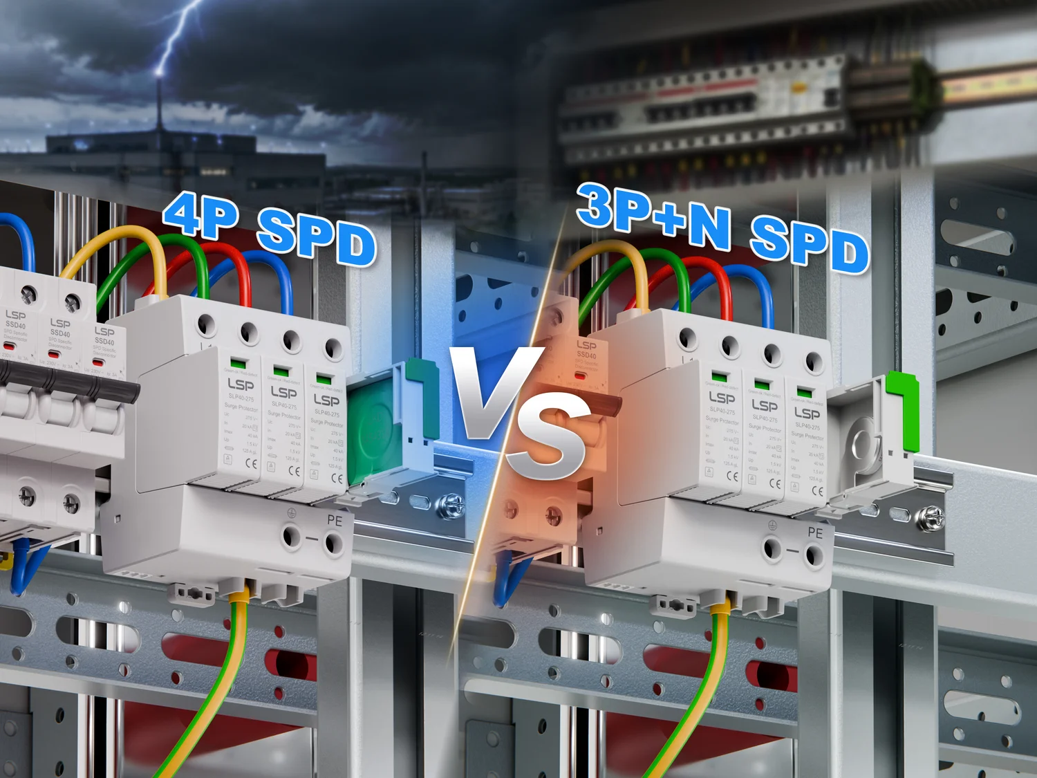
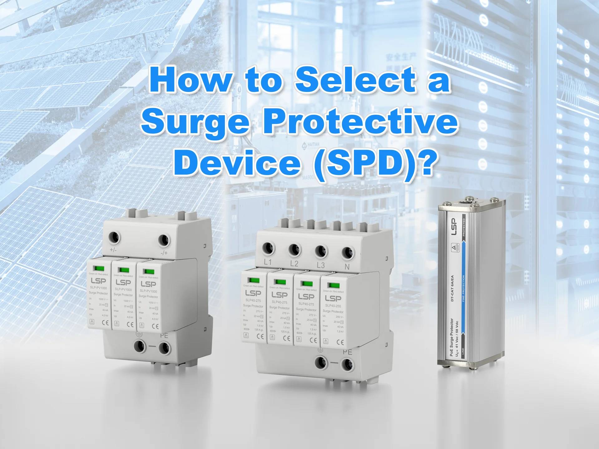
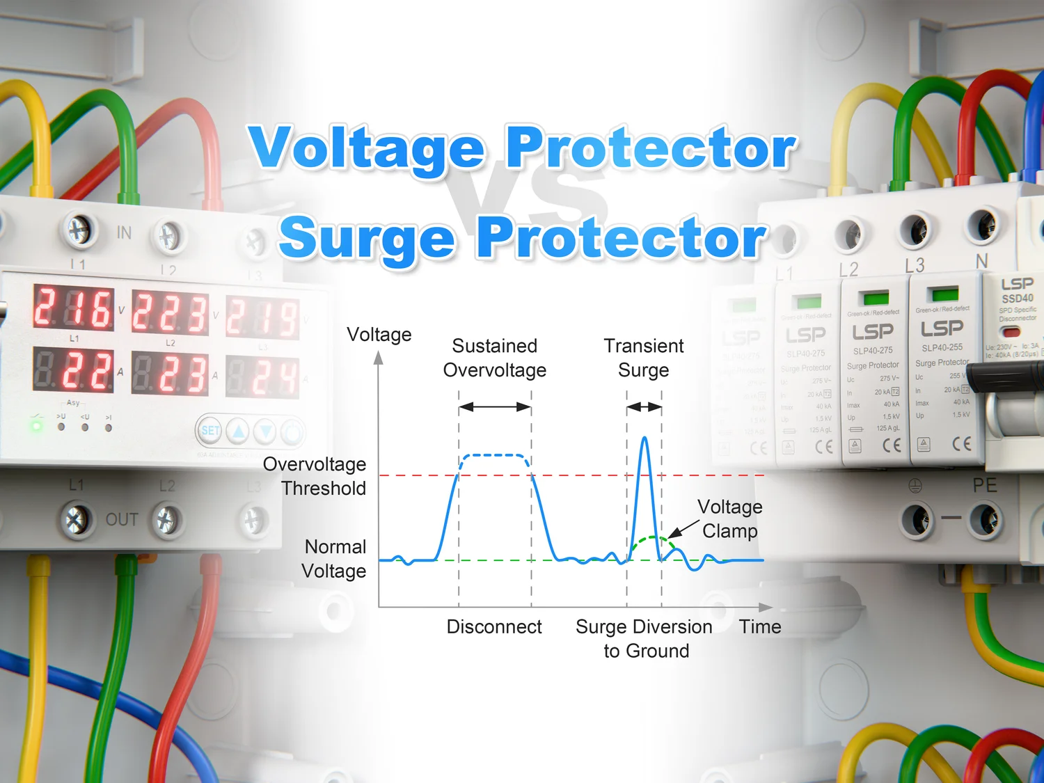
The incoming power feed of a PLC panel is a direct path for transient overvoltages, from lightning strikes and from switching operations on the same network, to reach the PLC power supply and I/O. A surge protective device (SPD) is one of the few components in the cabinet designed to sacrifice itself: it clamps the surge, absorbs the energy, and dies so the PLC does not.
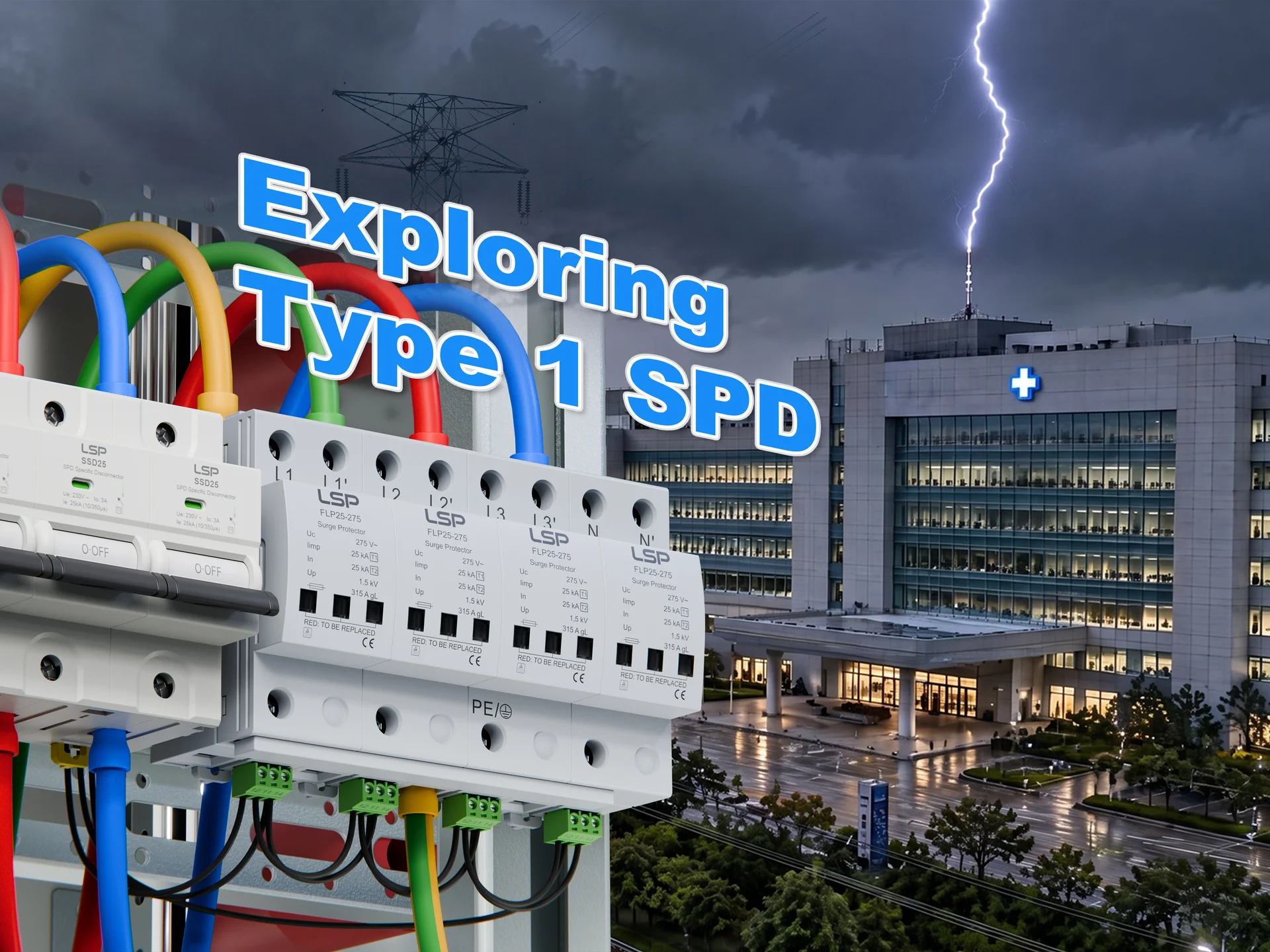
For a panel power feed, that means a Type 2 SPD, tested to the 8/20μs waveform, installed directly after the main breaker. The closer to the incoming terminals, the better. In IEC/EN 61643-11 terms (IEC, 2025), the mainstream ratings engineers actually specify are In 20kA nominal and Imax 40kA maximum discharge current, at 275V for standard IEC grids; Type 1 devices, tested to the much harsher 10/350μs waveform, belong at the building’s service entrance, not inside every panel.
Two quality red lines separate an SPD that protects from one that starts a fire. First, the heart of the device, the metal oxide varistor (MOV), must hold its parameters under repeated 8/20μs impulses. Cheap MOVs drift after a handful of hits: residual voltage rises and leakage current climbs until the device quietly becomes a load. The test data you want shows the same behavior after the tenth surge as after the first. Second, when an SPD reaches end of life, its disconnector must separate cleanly and extinguish the arc. A disconnector that leaves a molten filament of solder bridging the gap does not disconnect. It keeps conducting, heats up, and turns the protection device into an ignition source inside the cabinet. This is the difference between “the SPD sacrificed itself and the panel survived” and “the whole cabinet burned.”
Keep SPD leads short, use the manufacturer’s recommended branch protection, and remember the device’s discharge path finishes at the grounding system discussed next.
Wiring and Grounding That Outlive the Build
Wiring quality does not decide whether the panel works today. It decides whether someone can fix it at 2 a.m. five years from now. The test for every wire: can it be read, found, and replaced without tracing it through the entire cabinet?
Wire Routing: Ducts, Angles, and Separation
Run wires horizontally and vertically only. Diagonal runs are the difference between tracing a circuit in minutes and in hours. Keep power and signal separated, and when they must cross, cross at 90 degrees; CAN bus, Profinet, and analog circuits are the ones that misbehave when this rule is ignored (Simcona, 2023). Size ducts generously: field practice says nothing below 2″×2″, because ducts carry roughly double their original wire count over the panel’s life.
Label every wire at the end by the terminal it lands on; PLC I/O wires get the address syntax from the program. Use stranded wire with crimped ferrules on every terminal connection: ferrules prevent strand oxidation and vibration failures. Leave a little service slack at entry and exit points, hidden in the duct, not coiled in front of devices.
Grounding: One Point, One Busbar, Zero Loops
Mount a dedicated grounding busbar and bring every ground conductor to it, in the shortest practical path. Ground loops (multiple routes from device to earth) are the most common hidden cause of drifting analog readings, because loop currents offset signal references. Single-point grounding ends most of those investigations before they start.
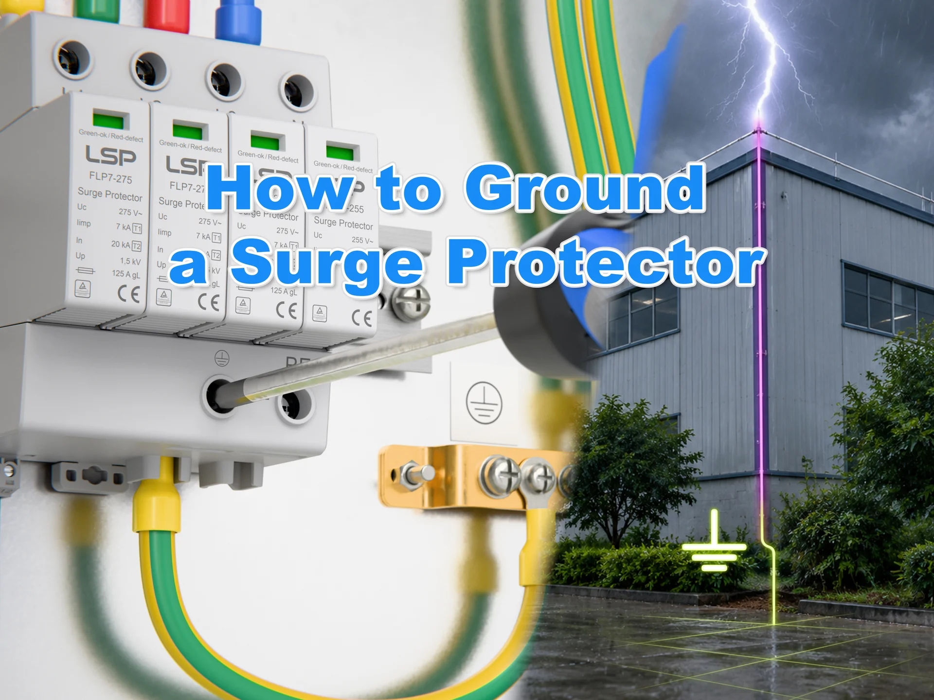
Shielded signal cables ground at one end only, at the PLC side. And the enclosure itself must be bonded: the cabinet’s metal shell is a safety barrier and, just as importantly, the low-impedance discharge path for any surge the SPD diverts. A Type 2 SPD without a solid panel ground is a valve with the outlet welded shut.
The Standards Your Panel Must Answer To
Standards are not a threat; they are a map of what inspectors will verify. Know which one governs your market before the first drawing, and the design depth follows from it.
| Standard | What it governs | Where it applies |
|---|---|---|
| UL 508A | Industrial control panel construction, SCCR, markings (UL Solutions) | North America (panels sold or installed in the US) |
| NFPA 79 | Electrical safety of industrial machinery (NFPA) | United States machinery builds |
| NEC (NFPA 70) | Conductor sizing, overcurrent protection, spacing | US installations |
| IEC 60204-1 | Electrical equipment of machines | Europe and IEC markets |
| CE / EMC Directive | Market access, electromagnetic compatibility | European Union |
| UL 1449 / IEC 61643-11 | SPD performance and test methods | The surge protector on your BOM, worldwide |
The same cabinet heading to the United States and to Europe faces two different paper trails: UL 508A inspection on one side, CE and EMC documentation on the other. The drawing package is where both are satisfied, which is why it pays to draw to the stricter market from the start.
Test Before You Power Up
Power-up is the last step, not the first. The hour spent on the checklist below routinely prevents a week of fault-finding later.
| Test | Method | What it catches |
|---|---|---|
| Point-to-point continuity | “Beep test” every wire against the schematic | Mislanded terminals before power is applied |
| Insulation resistance | Megger between conductors and ground | Damaged insulation, pinched wires |
| Ground continuity | Measure from every grounded component to the ground bus | Floating grounds that defeat the SPD and safety |
| Polarity check | Verify +24V / 0V at each terminal strip | Reversed power to sensors and modules |
| E-stop and safety loop | Operate mechanically, verify power removal, no PLC involved | A safety circuit that exists only in the program |
| Staged power-up | Control power first, then loads, section by section | Faults isolated instead of a single dramatic failure |
Record every result, along with the PLC program version and network settings. That file is the starting point for every future repair. For customer projects, this phase ends with the factory acceptance test (FAT), where the panel proves itself against the requirement list from the first section.
Build In-House or Outsource: The Decision Nobody Writes About
Search for “plc panel design” and you will find a dozen guides on layout and wiring. You will not find one on whether your company should be building the panel at all. Yet for OEMs and integrators, this decision is made before any of the above matters.
The divide is not whether you can build it; an electrician can wire a panel. The divide is repetition, quality control, and who absorbs rework. For one-off machine builds, in-house assembly gives control and iteration speed. For repeatable series production, a dedicated panel shop’s wiring consistency and throughput usually win, at the cost of your documentation quality becoming their build quality.
| Dimension | In-house build | Outsourced panel shop |
|---|---|---|
| Startup cost | Tools, test gear, trained staff | Near zero |
| Cost per panel | Falls with volume | Falls with volume, usually below in-house |
| Quality control | Your process, your fixes | Contract + inspection define it |
| Documentation demand | Internal drawings suffice | Drawings must reach wire-and-terminal level |
| Lead-time flexibility | High, you own the schedule | Depends on the shop’s queue |
Two control levers make outsourcing safe. First, the drawing package you hand over must be complete to wire and terminal level: every wire numbered, every component placed. A panel shop builds exactly what the drawings say; vagueness is converted into their cheapest interpretation. Second, lock the critical components (protection devices, PLC, power supplies) to named makes and models in the contract, or supply them yourself. The failure mode is well documented in this industry: certification samples that do not match production batches, because the shop found a cheaper substitute. The clause costs nothing, and it removes the one substitution that can burn a cabinet down a year later.
What Panel Design Really Means for the People Who Supply It
A locked BOM is only as good as the supply chain behind each line item. The panel is delivered once; then for the next thirty years, every outage, every lightning season, and every replacement part tests the promise made by each model number on that BOM. That is the second layer of engineering, and it follows directly from the red lines above.

Every design rule in this article holds only under two conditions. The components’ certifications are real, meaning the production batch matches the certified sample, and the substitution clause from the last section was not quietly defeated. And the protection devices actually deliver their self-sacrifice promise: the SPD’s MOV does not drift after ten surges, its disconnector separates cleanly, and the warranty behind it outlives the machine’s warranty. Both conditions are supply-chain properties, not drawing properties.
Read through that lens, the control panel business is a mix of project work and repeat stock: panel shops and machine OEMs build tens to hundreds of cabinets per project, procuring components in medium batches against an approved BOM. The buyers are the engineers who select parts and the purchasing teams who order them; the gate they must pass is drawing approval plus certification, UL 508A in North America and CE in Europe. And when a component fails in the field, the cost lands on the engineer who specified it and the project owner who signed for it. That is why every serious component vendor in this space competes on traceability first and price second.
For suppliers, that translates into concrete obligations. Quote against the BOM with specification sheets and certificate files, not just prices. Offer sub-certificates under your own certifications so an OEM’s panel approval moves faster. Hold core-component inventory deep enough that 10–15 day delivery is a promise you can keep. Stand behind products with a five-year warranty and same-day response, so the “who pays when it dies” question leaves the project’s risk register. And accept sample orders without minimums, because prototyping is how every panel project starts.
That is the profile worth looking for, and worth verifying in ten minutes. Manufacturers with full-range TUV, CB, and CE coverage, certified to IEC/EN 61643-11, and the ability to issue sub-certificates that accelerate a client’s panel approval. LSP, a surge protection manufacturer supplying panel builders and machine OEMs since 2010, publishes its certificate files and its range of AC surge protectors for panel power feeds online, which turns the verification above from a two-week email thread into an afternoon’s reading.
References
- IEC. “IEC 61643-11:2025 — Surge protective devices connected to AC low-voltage power systems.” 2025. https://webstore.iec.ch/en/publication/65314
- UL Solutions. “UL 508A Third Edition Summary of Requirements — Standard for Industrial Control Panels.” https://www.ul.com/resources/ul-508a-third-edition-summary-requirements
- NFPA. “NFPA 79 — Electrical Standard for Industrial Machinery.” 2024. https://www.nfpa.org/codes-and-standards/nfpa-79-standard-development/79
- Eabel. “PLC Panel Design: Safety, Layout & Best Practices.” 2025. https://www.eabel.com/plc-panel-design-safety-layout-best-practices/
- Simcona. “9 Control Panel Layout Design Tips for Safety & Performance.” 2023. https://simcona.com/blog/control-panel-layout-design
- AutomationDirect (via Processing Magazine). “Process control panel design basics.” 2022. https://www.processingmagazine.com/process-control-automation/control-panels-enclosures/article/21272400/process-control-panel-design-basics
- PLCTalk.net practitioners. “PLC panel standards” (2021) and “Control panel building” (2019). https://www.plctalk.net/forums/threads/plc-panel-standards.128284/ ; https://www.plctalk.net/forums/threads/control-panel-building.119684/