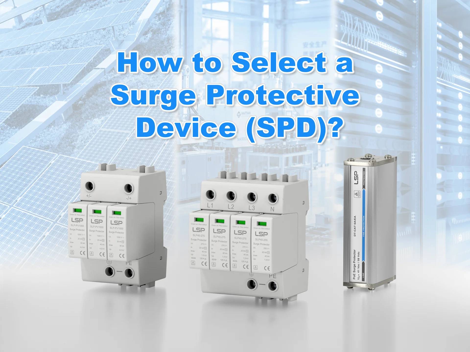
An Electrical Panel is the central hub of any industrial system, organizing multiple components to control machines and processes. Its design quality reflects engineering skill: poorly arranged panels with messy wiring are prone to early failure, while well-designed panels ensure reliable power distribution, controlled operation, and protection against electrical disturbances, including surges. Professional panels are resilient, prepared for normal operation and unexpected events. In industrial control environments, where uptime affects productivity, the reliability of an Electrical Panel is critical. The goal is to create a system that ensures safe, long-term performance for all connected equipment.
Introduction: The Mark of a Truly Professional Electrical Panel Design
The Electrical Panel embodies the control logic of an industrial system, distributing power and executing machine functions. The difference between a crude assembly and a professionally engineered panel lies in resilience and compliance with safety standards, not appearance. A professional panel operates reliably throughout its planned life and protects against common electrical hazards.
Reliability comes from a systematic design process that emphasizes safety, adherence to international standards, and elimination of potential failure points. In industrial operations, the integrity of an entire production line may depend on the correct specification and installation of a single protective element. Professional panel design ensures long-term operation, not just immediate functionality. This chapter explores key aspects of industrial Electrical Panel design, with emphasis on one of the most common threats: power surges, and discusses SPD integration as part of a resilient, optimized panel framework.
The Fundamentals of an Electrical Panel: Core Functions and Key Components
An industrial Electrical Panel serves two fundamental roles: distributing and controlling power, and protecting equipment and personnel from electrical hazards. A well-designed panel ensures that these roles are fulfilled efficiently, reliably, and safely.
Function 1: Power Distribution and Control
The panel receives the main incoming power feed and systematically subdivides, transforms, and distributes it to various system loads. Motors, sensors, actuators, heaters, and control devices all have specific voltage and current requirements. The Electrical Panel organizes this complex process, guiding energy to achieve operational tasks precisely and efficiently.
Function 2: Equipment and Personnel Protection
Electrical systems are vulnerable to faults like overloads or short circuits, which can release destructive energy. Protective devices, such as circuit breakers and fuses, interrupt dangerous conditions before they damage equipment or harm personnel. This protective role is essential for any safe and compliant design.
Key Components Should Know
- Programmable Logic Controllers (PLCs): Industrial-grade computers that control the system by processing inputs and triggering outputs according to programmed logic.
- Variable Frequency Drives (VFDs): Control AC motor speed accurately and save energy but are sensitive to electrical disturbances.
- Circuit Breakers and Fuses: Overcurrent protection devices interrupt circuits under fault conditions.
- Contactors and Relays: Electrically operated switches that connect low-voltage control circuits to high-power loads.
- Transformers and Power Supplies: Convert voltage levels for control circuits, separating AC and DC to prevent electromagnetic interference.
A professional designer understands each component’s role, operating limits, and how to combine them to create a reliable, resilient Electrical Panel.
Understanding Power Surges: The Hidden Threat to Electrical Panel Integrity
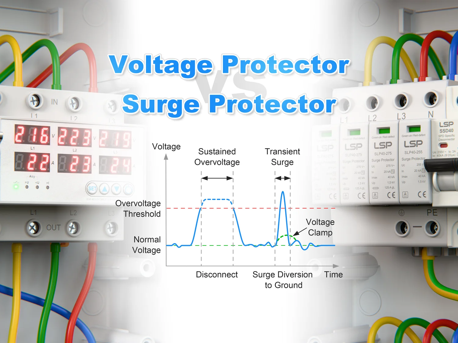
In addition to common hazards like short circuits and overloads, industrial Electrical Panels face a subtler yet highly damaging risk: transient overvoltages, or power surges. These brief, high-voltage spikes can result from nearby lightning strikes, switching of large inductive loads, or utility grid operations.
While robust motors may tolerate such events, sensitive devices like PLCs and VFDs are extremely vulnerable. A power surge can lead to immediate failure, gradual degradation, causing premature malfunction, or logic errors that interrupt production. Some effects may appear only weeks or months later, as intermittent or latent faults that are difficult to trace.
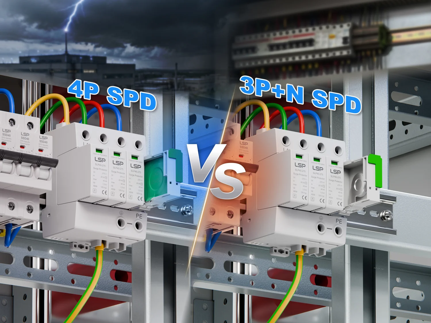
Integrating SPDs at strategic points within the Electrical Panel is essential to shield these critical electronics. Proper surge protection maintains system reliability, protects equipment, and ensures continuous operation in industrial environments.
Complying with International Standards: The Role of SPDs in IEC 61439 & 60204-1
Professional industrial Electrical Panel design is guided by international standards to ensure safety, reliability, and interoperability. Two key standards are particularly relevant: IEC 61439, which governs low-voltage panel assemblies, and IEC 60204-1, which addresses the electrical equipment of machinery.
IEC 61439 defines requirements for the Electrical Panel as a complete assembly, ensuring adequate internal space, mechanical robustness, electrical performance, and short-circuit withstand capability. IEC 60204-1 focuses on the safety of machinery and personnel, specifying in Chapter 7 that equipment must be protected against overvoltage caused by lightning and switching surges.
This requirement makes SPDs an essential element. Designers must evaluate and mitigate transient overvoltage risks to meet IEC 60204-1. While IEC 61439 regulates structural assembly, IEC 60204-1 mandates functional surge protection. A professional designer recognizes that SPDs are not optional—they are a necessary component for panels built to meet best-practice international guidelines, ensuring both safety and long-term reliability.
Step-by-Step Guide to Integrating SPDs in an IEC-Compliant Electrical Panel
Integrating SPDs into a professional Electrical Panel follows a systematic approach defined by the IEC 61643 series, ensuring correct selection and effective application.
Step 1: Selecting the Right SPD Type (1, 2, 3)

IEC 61643-11 defines three main SPD types based on installation point and energy-handling capacity:
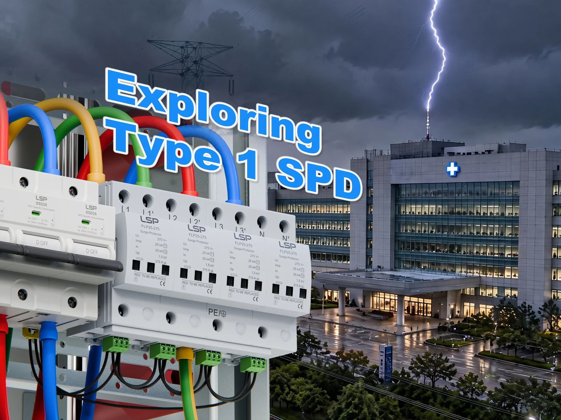
- Type 1 SPD: Installed at the main service entrance, this is designed to handle high currents from direct lightning strikes, redirecting most surge energy. Buildings with lightning protection systems require a Type 1 SPD at the source.
- Type 2 SPD: Mounted in sub-distribution boards or machine control panels, it mitigates residual overvoltage from upstream devices and internal facility surges. This is the most common SPD in industrial control panels.
- Type 3 SPD: Installed near sensitive loads, such as PLC power supplies, for point-of-use protection. It serves as the last line of defense against remaining transient energy, often rail-mounted inside the Electrical Panel.
SPD selection should follow a risk assessment considering lightning exposure, equipment sensitivity, and the architecture of the electrical system.
Step 2: Placement and Wiring Best Practices
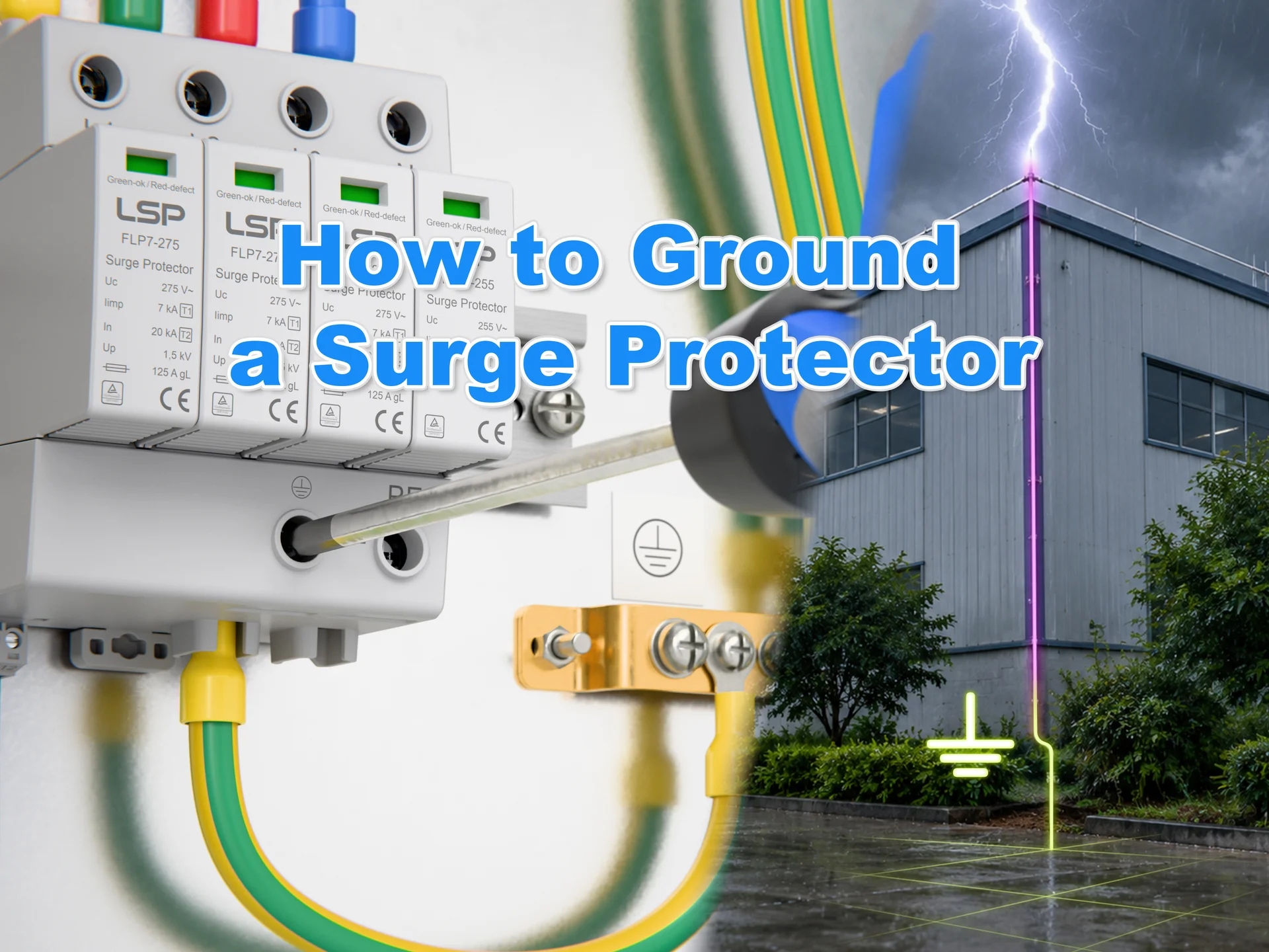
SPD effectiveness depends on installation quality. Connecting wires should be as short and straight as possible to minimize induced voltage from the wire’s natural inductance.
Long leads increase the let-through voltage (Up), reducing protection. Therefore, install the SPD as close as possible to the circuit connection point, such as the main breaker or busbars. Conductors to phase, neutral, and ground should be short, direct, and ideally bundled to reduce the inductive loop area. Proper placement and wiring are fundamental for effective surge protection.
Advanced Protection Strategies: Coordinating SPDs through Cascading
In facilities with high lightning exposure or mission-critical equipment, a single SPD may not provide sufficient protection. Multi-stage cascading protection enhances resilience by installing a Type 1 SPD at the service entrance, a Type 2 SPD in the distribution panel, and a Type 3 SPD near sensitive loads.
The effectiveness of cascading depends on the electrical impedance, mainly the inductance, of the wiring between devices. During a surge, the upstream Type 1 SPD activates first, diverting the majority of energy. The voltage drop along the conductor between Type 1 and Type 2 SPD allows the downstream SPD to absorb residual energy safely.
Proper cascading requires sufficient conductor length between stages. Without it, downstream devices may be exposed to energy beyond their rating. When coordinated correctly, each SPD absorbs energy appropriate to its design, sequentially sharing the surge current and minimizing voltage transients at sensitive electronics. This system-level approach maximizes protection for the Electrical Panel and connected equipment.
Conclusion and IEC Design Checklist: Building Resilient Panels

The physical realization of a well-designed Electrical Panel reflects a philosophy of resilience and professional engineering. Panels built according to international standards not only perform control functions reliably but also withstand electrical disturbances, ensuring equipment durability and personnel safety.
A professional designer can follow this IEC Design & Surge Protection Checklist to achieve a resilient panel:
- Risk Assessment: Evaluate the need for surge protection per IEC 60204-1 based on installation location and exposure.
- Standard Compliance: Ensure enclosure, SPD, and all components meet IEC standards (IEC 61439, IEC 61643-11).
- Proper SPD Selection: Choose the correct SPD type (1, 2, or 3) based on risk assessment and location in the distribution system.
- Coordination (Cascading): For multiple SPDs, confirm sufficient conductor length and impedance for energy coordination.
- Short-Circuit Current Rating (SCCR): Verify the SCCR of the SPD and overcurrent protection exceeds the available fault current.
- Optimal Placement: Install the SPD close to the power bus connection to minimize lead length.
- Minimized Lead Length: Keep connecting conductors short, direct, and, where possible, bundled to reduce inductance.
- Proper Conductor Sizing: Follow manufacturer guidance and electrical standards.
- Clear Labeling: Ensure the panel and SPD are clearly labeled with warnings and ratings per IEC 61439.
- Detailed Documentation: Include schematics, component specs, SCCR calculations, and SPD compliance certificates with the panel.
By systematically addressing these points, designers ensure the Electrical Panel meets professional standards, delivers long-term reliability, and provides effective protection against unpredictable electrical disturbances.
Beyond the Component: Partnering for IEC-Compliant SPD Solutions

Since 2010, LSP has focused on the research and manufacturing of SPDs, emphasizing international compliance. Our complete SPD portfolio is designed and tested in accordance with IEC/EN 61643-11 standards and is supported by ISO 9001, TUV, CB, and CE certifications. Each unit not only meets strict performance criteria but also helps customers simplify compliance for global projects and competitive tenders. With an annual production capacity of 300,000 units and a rigorous quality management system, we provide reliable protection for Electrical Panels, enabling smooth market entry worldwide.
Partnering with LSP means collaborating with a team that deeply understands international standards. Beyond supplying SPDs subjected to lightning current impulse testing, thermal stability checks, and long-term durability assessments, we offer tailored solutions and certification support. From early risk assessment and SPD selection to preparing compliance documentation, our experts streamline the entire process. This approach saves time, reduces certification costs, and accelerates product differentiation and global expansion with confidence.
Frequently Asked Questions (FAQ) on Electrical Panel Design with SPDs
What role does an SPD play in an Electrical Panel?
An SPD limits transient overvoltages and protects sensitive electronics, such as PLCs and VFDs, from lightning-induced and switching surges. By redirecting surge current to the ground, it safeguards both equipment and personnel.
How do I select the correct type of SPD for my panel?
Selection depends on risk assessment, equipment sensitivity, and installation point. IEC 61643-11 defines three types: Type 1 at the service entrance, Type 2 in distribution panels, and Type 3 near sensitive loads for final point-of-use protection.
Can a single SPD provide full protection against surges?
For panels exposed to lightning or critical equipment, cascading SPDs (Type 1 → Type 2 → Type 3) is recommended. Proper coordination ensures each device absorbs surge energy sequentially, minimizing residual voltage at sensitive loads.
What are common mistakes when installing an SPD?
Long connecting leads, poor grounding, or lack of coordination with overcurrent protection can reduce effectiveness. Keep conductors short (<50 cm), direct, and properly grounded. Ensure SPD type and placement match the risk assessment.
How can I verify an SPD is functioning properly?
Most SPDs have status indicators. Green typically means operational. Regular inspections and functional tests are recommended to ensure continued protection.
Why is risk assessment important for SPD integration?
Risk assessment identifies lightning exposure, equipment sensitivity, and panel architecture. It guides the correct selection, type, and placement of SPDs to ensure compliance with IEC 60204-1 and maximum protection.
Can SPDs protect both direct lightning and internal switching surges?
Yes. When Type 1, 2, and 3 SPDs are correctly coordinated within the panel’s electrical distribution, they effectively manage both direct lightning strikes and residual internal surges.
How does proper SPD placement impact panel reliability?
SPDs must be as close as possible to connection points. Short, direct leads reduce voltage induction and maximize protective performance, ensuring the Electrical Panel operates reliably under surge events.