A battery energy storage system is more than a shipping container full of lithium-ion cells. Between the battery racks and the grid connection sits a chain of power, control, and protection components, and every one of them has to be specified, coordinated, and certified before a project clears design review.
This guide walks through the components of a battery energy storage system (BESS) in the order they actually matter for design: the energy-carrying hierarchy, the control layer, the supporting subsystems, and the layer most component lists gloss over, electrical protection. By the end, you will also see how these design choices translate into procurement decisions on real projects.

From Cell to Container: The Building Blocks of a Battery Energy Storage System
Every BESS is assembled as a strict hierarchy, and the vocabulary matters because each level adds a new management responsibility.
Cells are the smallest unit. For stationary storage, lithium iron phosphate (LFP) is now the dominant chemistry. Its nominal 3.2 V per cell, higher thermal runaway threshold, and long cycle life (commonly rated at 6,000-8,000+ cycles) fit the duty profile of a system that must run for 15-20 years (NextG Power, 2025). Cells are combined in series and parallel into modules, which fix a system’s voltage and capacity building blocks.
Modules are stacked into racks, the level where DC bus voltages climb into the hundreds of volts, up to 1,500 V DC in modern designs. Racks are finally installed in containers or cabinets: standard ISO containers for utility-scale projects, purpose-built cabinets for commercial and industrial sites. The enclosure is where environmental control, fire safety, and electrical segregation come together.
Two numbers frame everything downstream. First, grid-scale BESS are generally designed to deliver full rated power for 1-4 hours (Wikipedia). Second, how long a BESS battery “lasts” is really two questions: cycle life (how many full charges it can deliver) and calendar life (how it degrades with age regardless of use). Both are strongly temperature-dependent, which is why the next two sections matter.
One scope note: this section covers the energy path. The control layer, thermal and fire subsystems, and electrical protection each get their own treatment below.
The Three Brains of a BESS: BMS, PCS, and EMS
A BESS runs on three separate control systems, and most confusion about components comes from blurring their jobs. The cleanest framework: the BMS keeps the battery alive, the PCS moves power in and out, and the EMS decides when that should happen.
Battery Management System (BMS)
The BMS is the first line of defense, and it is far more than a fuel gauge. It continuously monitors each cell group for overcharge, over-discharge, over-temperature, and overcurrent. It also estimates state of charge (SOC) and state of health (SOH) and keeps cells balanced. Large systems run a three-tier architecture (cell, module, and rack level) with sampling accuracy in the ±10 mV range and protection responses measured in milliseconds. If the BMS flags a fault, it commands the relevant rack to disconnect and triggers the fire suppression system; the PCS receives the shutdown signal through the same chain.
Think of it as an ICU monitor: it watches every vital sign around the clock and intervenes automatically before a condition becomes critical.
Power Conversion System (PCS)
The PCS is the bidirectional converter between the DC battery bus and the AC grid. Unlike a PV inverter, it converts in both directions: charging as a rectifier, discharging as an inverter. It must also support grid-tied and off-grid operation. Selection hinges on a few hard parameters: the DC voltage platform must match the battery rack voltage (1,000 V or 1,500 V designs), the communication interface must talk to the BMS and EMS (typically Modbus TCP or CAN), and the unit must be grid-following or grid-forming depending on whether the site must be able to run as an island.
If the BMS is the safety officer, the PCS is the throttle and brake pedal, and it takes its setpoint from the EMS.
Energy Management System (EMS)
The EMS is the plant-level dispatcher. It decides charge and discharge strategy based on the revenue or savings case: peak shaving, time-of-use arbitrage, frequency response. It sends power commands to the PCS, while the SCADA layer handles supervision and data collection. Where the BMS reacts in milliseconds, the EMS plans in minutes and hours. That division of timescales is the simplest way to explain why both exist and why neither replaces the other.
Keeping Cells in Their Comfort Zone: Thermal Management and Fire Suppression
Battery life and battery safety are both, at root, temperature problems: cells like a working band of roughly 15-35 °C, and thermal runaway is the terminal risk.
| Solution | How It Works | Typical Fit |
|---|---|---|
| Air cooling (HVAC) | Forced airflow through racks | Cabinet-scale and smaller C&I systems |
| Liquid cooling | Coolant plates and loops against modules | High-density utility-scale containers |
| Aerosol suppression | Condensed aerosol floods the enclosure | Cabinet BESS |
| Clean-agent (Novec/FK) suppression | Inert agent displaces combustion | Container BESS |
| Water-based suppression | Cooling and isolation per NFPA 855 guidance | Large outdoor installations |
The fire system is the last line of defense. But prevention happens earlier in the chain: in the BMS catching a faulty cell before it climbs, and in the protection devices that interrupt a fault before it becomes a fire. That hand-off is the subject of the next section.
The Protection Layer: Fuses, Breakers, and Surge Protection in BESS Design
Here is the point most generic component guides skip. Protection in a BESS is not a parts list. It is a coordination problem, because the DC side behaves differently from anything in conventional AC distribution.
Two facts drive everything. First, the battery DC circuit can deliver extremely high short-circuit currents: 100 kA and beyond in large designs, with BESS fuses now available with DC breaking capacities up to 250 kA at 1,500 V DC, 2022. Second, DC arcs have no natural zero crossing, so a protection device must extinguish the arc itself. And a battery source behaves differently at end of life than a PV source does, which is why PV-rated parts are not automatically BESS-rated.
Overcurrent Protection on the DC Side
The DC side uses two device families in complementary roles. Fuses provide the final, one-shot breaking capacity. They are sized with a voltage rating at or above system voltage and a breaking capacity above the prospective short-circuit current at the installation point. DC circuit breakers handle the resettable, operational side. A complete design places protection at three levels: the rack, the DC bus, and the PCS DC input, with time-current curves coordinated so the nearest device clears a fault first (selectivity).
The division is like a fire crew: the fuse sacrifices itself to put out the fire once; the breaker is the crew that can stand down and go again.
AC-Side Protection and Switchgear
The AC side is more familiar territory, but a BESS changes two assumptions. Power flows in both directions, so protection must be sized for charging as well as discharge current. And because a grid-forming inverter can keep energizing a dead feeder, anti-islanding protection (rapid, automatic disconnection under IEEE 1547 rules) is a hard requirement, not an option (UL Solutions). Standard AC breakers, the step-up transformer, and ground-fault protection complete the chain.
Surge Protection: Where SPDs Fit in a BESS
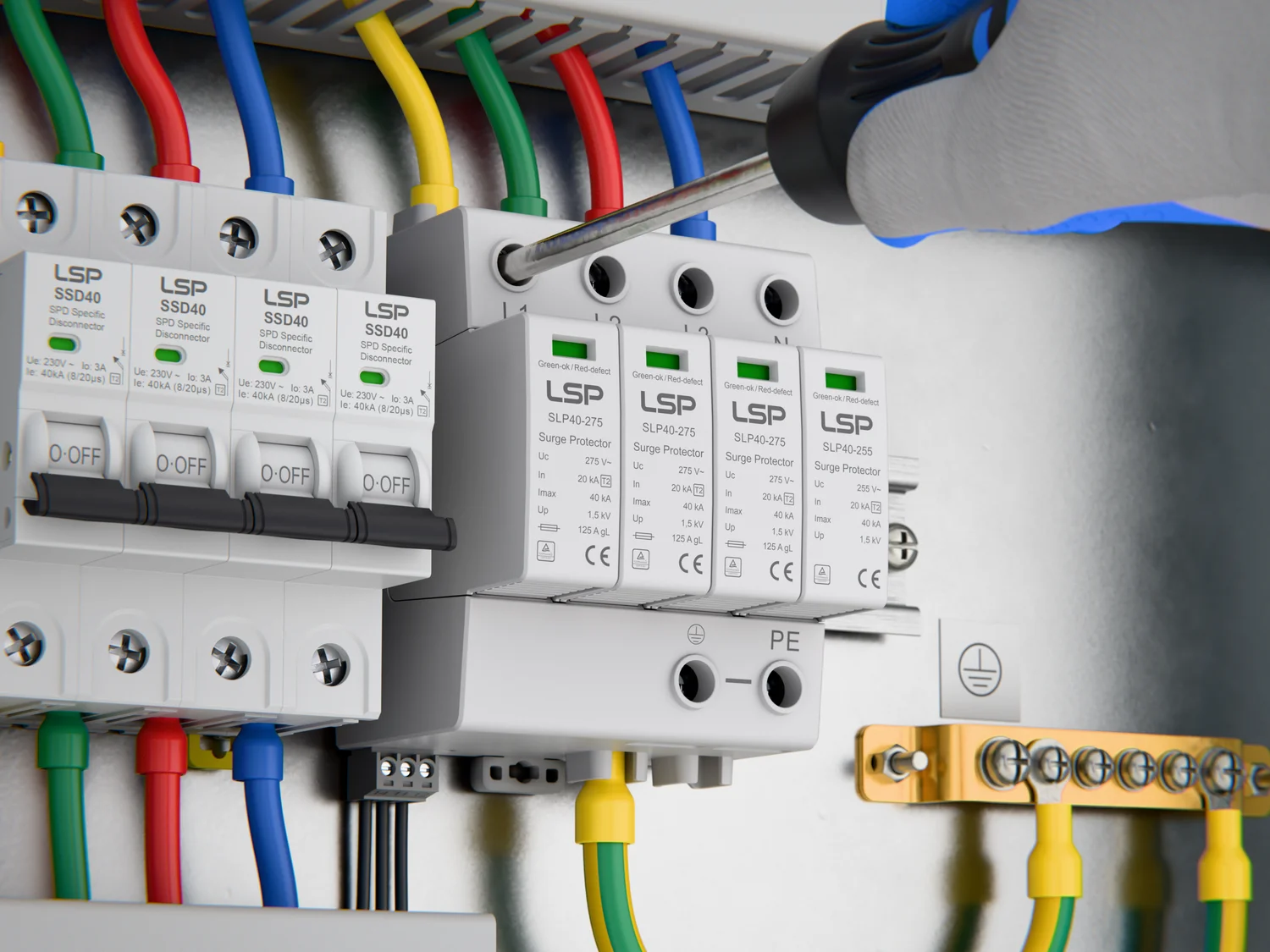
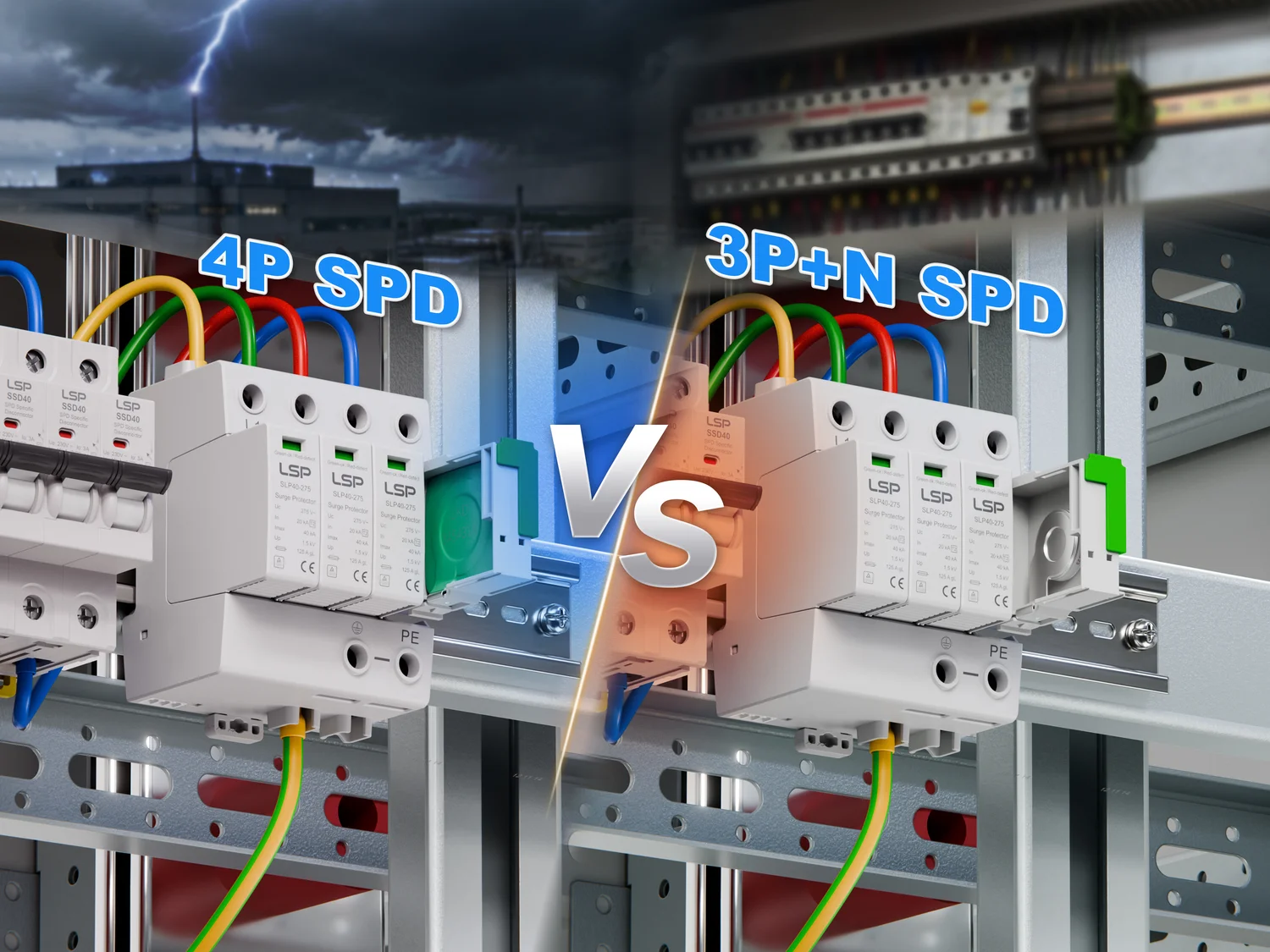
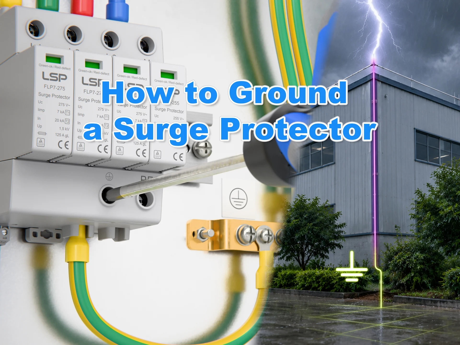
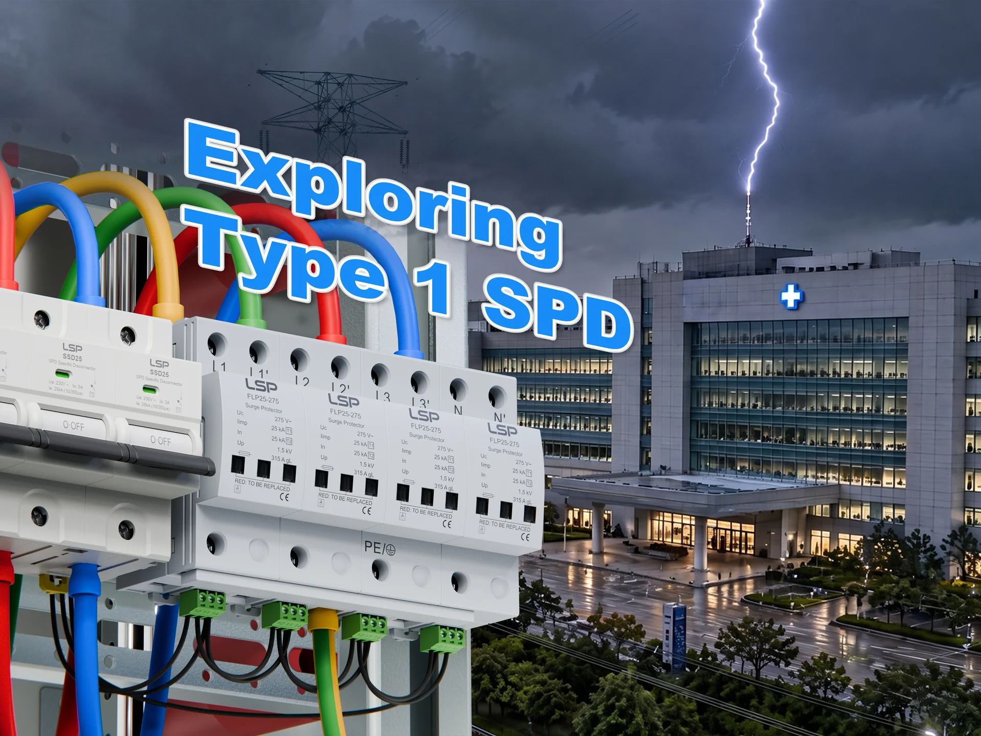
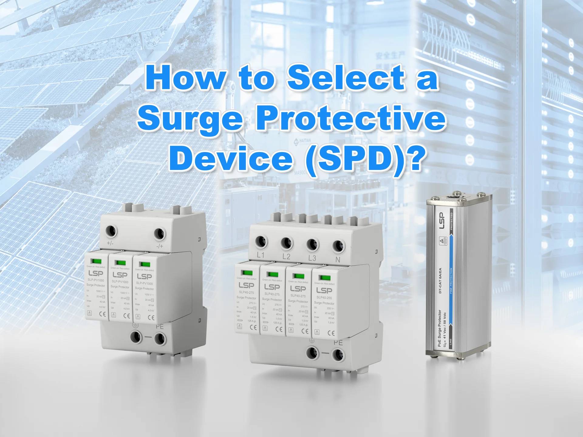
Surge protection deserves its own design step because a BESS concentrates sensitive, low-withstand-voltage electronics behind very long DC and AC cable runs, exactly the geometry that lightning-induced transients like. The IEC 62305 framework breaks the threat into four scenarios: a direct strike to the structure, a strike nearby, a strike to the incoming lines, and induced surges on those lines.
On the AC side, the rule set is mature: where a lightning protection system (LPS) is installed, Type 1 SPDs are required at the service entrance; where the incoming lines are overhead, Type 1 is mandatory regardless. On the DC side, dedicated standardization is newer: IEC 61643-41, covering SPDs on low-voltage DC power lines, is still in draft circulation. That makes vendor engineering discipline more important, not less.
The working selection criteria for a BESS DC-side SPD distill to four checks:
The last criterion is where BESS diverges from PV. The battery can source fault current in the 100 kA class, so an SPD that survives a PV string short circuit may still fail on a battery bus. The same logic applies to the voltage protection level: the SPD’s Up must sit below the equipment’s impulse withstand voltage Uw, which for battery electronics is often lower than designers assume.
Designing a BESS: From Load Profile to Architecture
Component knowledge becomes a design when you can take it from a blank page to a reviewable single-line. The working order is: size first, architect second. And sizing starts with the revenue model, not the battery brand.
Sizing the System: Power, Energy, and Duration
Four steps get the headline numbers right:
- Define the application. Frequency response is a power-first job; arbitrage and peak shaving are energy-first. The revenue case dictates the duty cycle before any component is chosen.
- Fix the power (MW). Sized from the peak load to be served or the response the grid contract requires.
- Fix the energy (MWh). Energy equals power times duration, E = P × t, and grid-scale systems typically land in the 1-4 hour band.
- Apply margins. Depth-of-discharge limits (often 80-90%) and annual capacity fade must be reserved up front, or the system under-delivers by year five.
Choosing an Architecture: AC-Coupled, DC-Coupled, and Container Layout
Architecture choice follows the sizing numbers. AC-coupled systems use a dedicated battery inverter and retrofit easily alongside an existing PV plant. DC-coupled systems share the DC bus with solar and save one conversion stage. Layout follows the same logic: battery rooms are physically segregated from electrical rooms, maintenance aisles and cable routing are planned before racks land, and the grounding and equipotential bonding scheme is set by the applicable installation code.
| Dimension | AC-Coupled | DC-Coupled |
|---|---|---|
| Conversion stages | Two (PV DC-AC, battery DC-AC) | One shared DC bus |
| Retrofit friendliness | High — independent of existing inverter | Low — requires DC-side integration |
| Efficiency | Slightly lower at partial load | Slightly higher at rated load |
| Typical fit | Retrofits and multi-asset sites | New-build solar-plus-storage |
Standards and Compliance: The Certifications That Gate a BESS Project
Standards are the entry ticket to any grid-scale or C&I project, and the map differs by market:
| Standard | What It Governs | Primary Market |
|---|---|---|
| UL 9540 | Overall energy storage system safety | North America |
| UL 9540A | Thermal runaway fire propagation testing | North America |
| NFPA 855 | Installation and fire safety requirements | North America |
| IEC 62619 | Safety of industrial battery cells and packs | Europe and international |
| IEC 62477 | PCS safety | International |
| IEEE 1547 | Grid interconnection | North America |
Two practical points. First, NFPA 855 requires lithium-ion systems above 20 kWh to be listed to UL 9540, so the certificate chain starts at the equipment level, not the project level (Mitsubishi Electric, 2026). Second, UL and IEC certifications are not interchangeable: a project targeting both markets needs both tracks. When procuring, request the complete certificate chain, not a summary sheet. It is the difference between a supplier who has been through the process and one who is about to.
What BESS Design Choices Mean for Your Business
Every technical choice in the sections above has a second, commercial reading: the same facts, seen from the procurement side.

The design workflow described here applies to a specific business reality: utility-scale and commercial projects are engineered and procured as projects (bulk orders with design approval gates and market-specific certification requirements), while cabinet-scale products move as semi-standard stock. The buyers are design engineers, EPCs, and system integrators. The failure cost of a bad protection choice lands on the integrator, not the component vendor.
That allocation of risk explains three procurement behaviors you can observe on any serious project. Protection components and certifications function as trust anchors. After the four SPD criteria and the certificate-chain check in the previous sections, a parts supplier without full documentation simply does not make the shortlist, regardless of unit price. Lead time and batch consistency matter more than a last-percent price discount. A container assembly line stops when one rack-level protection device is missing. And warranty terms are the mechanism by which integrators transfer risk downstream, which is why the 2-year warranty common in the industry and the longer commitments of established manufacturers are priced differently in bids, even for identical-looking parts.
For the protection layer specifically, supplier credentials do the heavy lifting. LSP, a surge protection manufacturer serving energy storage integrators, publishes its full certificate coverage: TUV, CB, and CE for its AC and DC surge protective devices, tested to IEC/EN 61643-31. That lets design teams drop certified protection components into a BOM without re-running qualification themselves.
References
- UL Solutions. “Your Guide to Battery Energy Storage Regulatory Compliance.” https://www.ul.com/resources/your-guide-battery-energy-storage-regulatory-compliance
- Mitsubishi Electric. “Understanding the UL 9540 Listing.” 2026. https://mitsubishicritical.com/resources/blog/understanding-the-ul-9540-listing/
- Wikipedia. “Battery Energy Storage System.” https://en.wikipedia.org/wiki/Battery_energy_storage_system
- NextG Power. “The LFP Battery Life Cycle: Understanding 8000 Cycles and 70% SOH.” 2025. https://nextgpower.com/the-lfp-battery-life-cycle-understanding-8000-cycles-and-70-soh/